


noseman
-
Posts
120 -
Joined
-
Last visited
-
Days Won
7
Content Type
Profiles
Blogs
Forums
Gallery
Pipeline Tools
3D Wiki
Plugin List
Store
Downloads
Videos
Posts posted by noseman
-
-
You should be able to just rotate the Wrap, or the Deformed model. Alternatively you could use the Shrink Wrap Deformer or even the Bend Deformer.
If we can't see the problem, I can't easily provide a solution without speculation.Could you please post a simplified scene?
Cheers
1 -
1 hour ago, jed said:
...Radian does not 'include' pi IMHO...
...changes username to Mr Pedantic...
I think our difference is a philosophical one. Yes, Radians are measures of angles, and as such stand by themselves, but it is that way BECAUSE of Pi.
If the ratio between the Radius and the Circumference was not the same for all circles, a consistent Radian couldn't exist, as it would express a different result for different Circles.
Did I just up the Pedante?
0 -
1 hour ago, jed said:
..pi doesn't really come into this calculation. Radian does not 'include' pi IMHO.
I meant that in the sense that 2π radians is equal to 360 degrees. So for a full rotation of the wheel, we have 2 Pies... hence the pie is very tasty.
Just in case I wasn't clear.
0 -
Doh...
Note to myself: Hey noseman, it's because a Radian includes the Pi already... TWICE. That's why Radians are the default rotation unit...
Thanks Jed...
0 -
All above solutions can work great, and here's my input:
I'm using a Tracer Object, to trace a Cube (Turn Off Trace Vertices in the Tracer Attributes). This will generate a Spline and record the Cube's Trajectory (You can animate the cube by any means and I have chosen a Vibrate tag because I'm lazy).
Then we use XPRESSO to read the length of the Tracer Spline, as it reflects the distance travelled.
I use that as an input to a Range mapper that takes the Circumference of the Wheel (2*Pi*Radius), and maps that to one Radian (Negated because the wheel is going "the other way").
I then put that back into the Wheel P Rotation as Radians (Default Rotation Unit for XPRESSO).
I also use an "Align to Spline" Tag to align the wheel to the end of the spline, and set it to Tangential so that it follows the Spline Tangent and orient itself. The Tracer offers the ability to create wheel tracks as well.
Fun!!!
2 -
8 hours ago, snakeEater said:
Thank you and grab a subscriber
You're welcome and thank you very much!
0 -
You're Welcome!
0 -
There's the easy way, and then the easier way. I'm sure there's an easiest as well...
2 -
Funny enough, the slightly more complex nature of setting up our cloth compared to the simpler of Blender, actually allows us more control for setups like these. And let's not forget that this Cloth system, was developed nearly 20 years ago!!!
I love being wrong in that way too... although it never really happens
 2
2 -
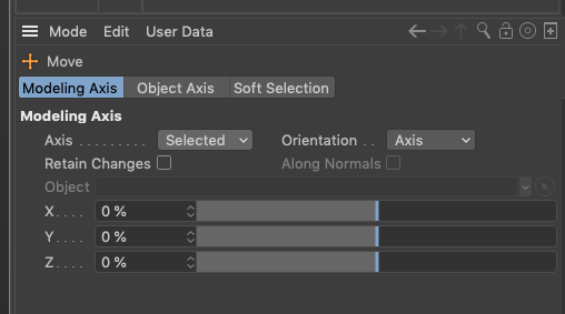
Select your Move tool, and look at the Attribute manager, inside the "Modeling Axis" Tab. Change the Axis to "Selected" (Default), or anything else you think is appropriate. I bet you have "World" Selected.
 1
1 -
I'm terribly sad to say that Cerbera is... WRONG!!!
My latest Video on my Youtube channel has the solution. SUBSCRIBE!
3 -
Just to make it clear, this helix problem is a known issue and not something wrong with your setup.
0 -
And to be very fancy, you could even use the Formula Spline for the main spiral shape and a Rail spline, then pipe it through a MoSpline and finally in the Sweep... just saying.
https://www.dropbox.com/s/mz9xca6m16oc3uf/spiral formula 01A.c4d?dl=0
0 -
We actually have a tool that does precisely that... and more!
It's the "Matrix Extrude" TOOL NOT the MoGraph Modifier. Find it in the Mesh Menu or via the Commander.
Make sure you uncheck "Polygon Coordinates"...
2 -
and here's a file you can check out:
0 -
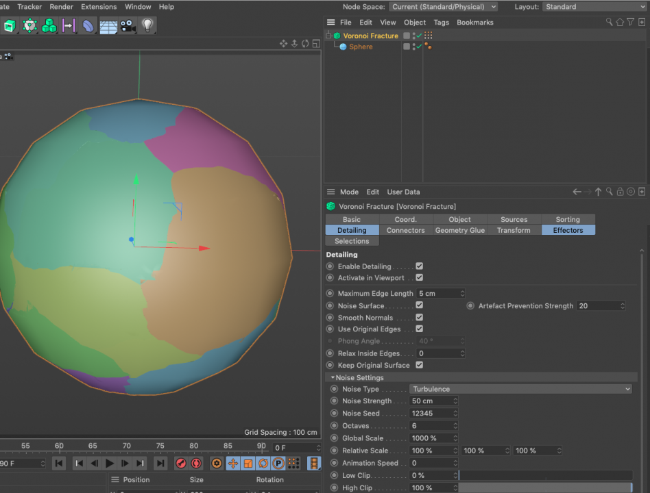
You have to increase the Noise Strength under the Noise Settings.
But beware, too much and the edges may fold on themselves.
 1
1 -
Just increase the subdivision parameter of the Helix to a large amount
0 -
Unfortunately this is a known issue, and although there's a way to make the problem less visible, you may not be able to totally eliminate it.
Make a cut to isolate the part of the road that clips under the Camera View, and then go and subdivide that polygon a few several times.
THEN go and Generate the UVW Coordinates.
Another method, which will work for the original geometry but won't help you if you're going to fracture it, is to make a Copy of the Solved Camera on frame 0, remove all keyframes and use that one as the projecting camera.
You may need to crop the final render to remove any gaps in both methods.
Here's the Road Polygon Object with "correct" UVs. Just copy and paste it to your document and apply the material using UVW
https://www.dropbox.com/s/lubkzxki7k2i0hx/Road.c4d?dl=0
Cheers
Noseman
0 -
Another thing I just realized looking at your video, is that the Springs are the only elements that define how the Trunk bends. Since the spring doesn't have a defined connector point, and is compressible, this allows for a lot of chaos in the movement. I feel you will never be able to create a mathematically correct correlation between the 2 rigs.
This reinforces my previous proposal, to create a table of correlations.
1 -
The problem here is that you are using two completely different "mechanisms" to drive the two rigs.
IK and FK, just calculate Rotations of Joints... NOTHING Else. In FK the rotation IS the driver, but in IK the Goal position defines the rotations.
Your Robot, uses NO rotational information whatsoever.
The only way I see you have parity between the two systems, is either try and replicate the Model inside Cinema 4D using some sort of Dynamics, Connectors e.t.c., OR find a correlation between parts of the Cinema 4D Rig (Joint rotations) and your controller motors.
So for example:
Make a pose inside C4D. Then try to manually replicate that pose using your controllers. When you're satisfied with the result, compare all the rotations on the Joints, and the Parameters of your Motors (how much did they rotate, and which ones).
By doing this, you may be able to find a correlation between the two systems that's close enough for your Project.
I would start by posing the tip of the nose, as it involves fewer moving parts.
Nice Project. Good luck!
1 -
Cineversity Live stream September 11th 2018
Tuesday September 11th, 1pm Eastern (10am Pacific), I'll be live online for an hour or two, to show off some Cinema 4D R20 tips and tricks, and answer user questions.
Tune in on Cineversity YT channel:https://www.youtube.com/watch?v=Pr1hVkjuTJ0
Feel free to ask questions here and maybe I'll cover some of them…
1

Wrapping an object on tube top to bottom
in Modelling - Do Not Post Here
Posted
We're also very smart and good looking too... so there you have it.
You're very welcome!