

Cesar
-
Posts
46 -
Joined
-
Last visited
-
Days Won
4
Content Type
Profiles
Blogs
Forums
Gallery
Pipeline Tools
3D Wiki
Plugin List
Store
Downloads
Videos
Posts posted by Cesar
-
-
Actually, the effector changes the local matrix scale.
For example, a Cube scaled by 2 in X would be : (2, 1, 1)
You need to get this scale and multliply the input cube size by it :
Cube size = 100 cm * (2, 1, 1) = (200, 100, 100)
The result cube is now a frame with the correct size, but there is still the local matrix scale that can't be changed because it depends of the effector. The final cube size looks like 400 cm in X because of the 2 scale factor
So we need to fix it by multiply the cube geometry by the invert of the scale to artificially "reset" the matrix scale
Cube geometry size = (200, 100, 100) * ( 1 / (2,1,1) ) = (100, 100, 100)
And as the local matric scale is still (2,1,1), the result looks like the correct 200 cm, 100 cm, 100 cm :

But carefull with this trick, because it can generate precision artifacts with big scale values (if the scale is 100000, the geometry will be 0.00001 cm, so we can loose precision because of the float limit (see https://en.wikipedia.org/wiki/Floating-point_arithmetic ))
1 -
20 minutes ago, zeden said:
A capsule like that? User the User data slider for frame size. If someone knows how to propagate the float node input as user data slider without xpresso I would love to know!
I really love the Node Mesh solution. But when the cube is scaled by an effector, the result is deformed.
I think if would be good if the Size cube parameter is multiplied by its local scale matrix (but I don't know very well the node editor to do that lol)
0 -
Very interesting indeed !
Even if I don't see solution without a script, here is a version with a Python generator :
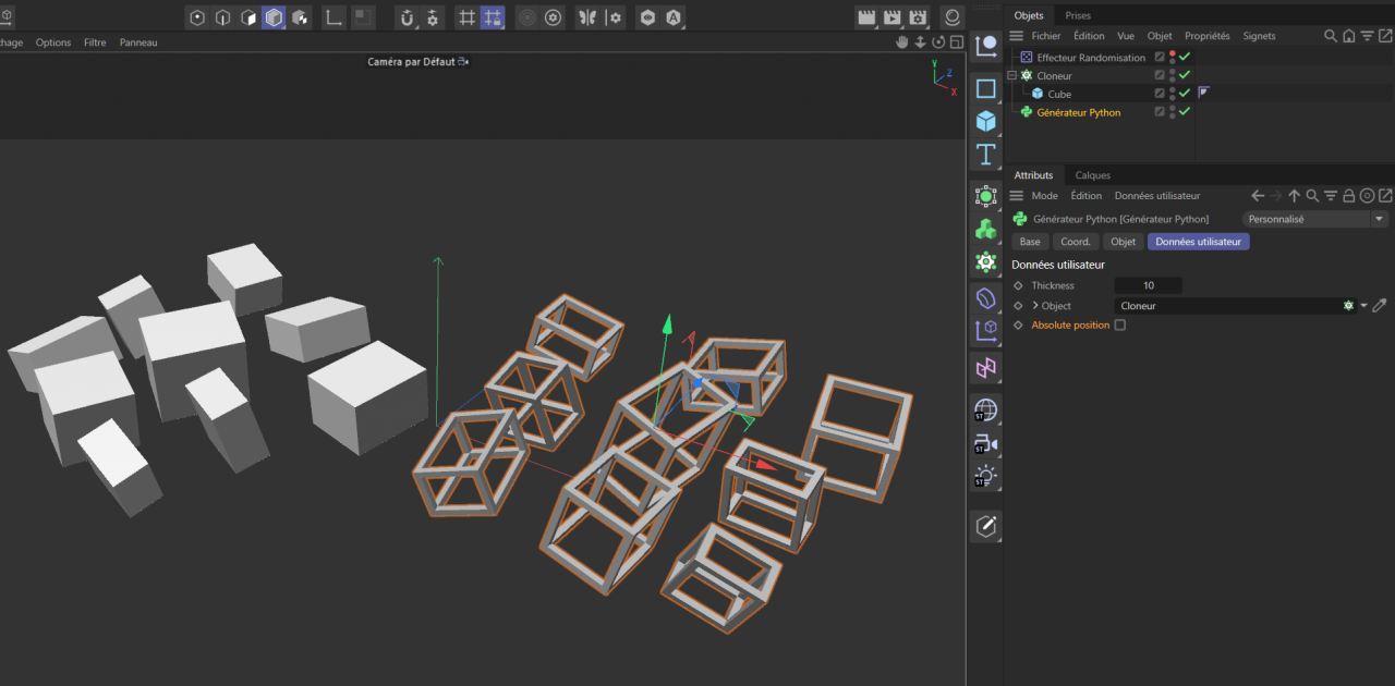
from typing import Optional import c4d from c4d import Vector, CPolygon doc: c4d.documents.BaseDocument # The document evaluating this python generator op: c4d.BaseObject # The python generator hh: Optional["PyCapsule"] # A HierarchyHelp object, only defined when main is executed def DoRecursion(op, callback, params): tp = op.GetDeformCache() if tp is not None: DoRecursion(tp, callback, params) else: tp = op.GetCache() if tp is not None: DoRecursion(tp, callback, params) else: if not op.GetBit(c4d.BIT_CONTROLOBJECT): if op.IsInstanceOf(c4d.Opolygon): callback(op, params) tp = op.GetDown() while tp is not None: DoRecursion(tp, callback, params) tp = tp.GetNext() def CreateFrame(obj, params) : frame = c4d.BaseObject(c4d.Opolygon) mg = obj.GetMg() rad = obj.GetRad() mp = obj.GetMp() mg.off = mg.Mul(mp) sx = rad.x sy = rad.y sz = rad.z scale = mg.GetScale() sx *= scale.x sy *= scale.y sz *= scale.z ep = params['thickness'] ix = sx - ep iy = sy - ep iz = sz - ep pts = [ Vector(-sx, -sy, -sz), Vector(-sx, sy, -sz), Vector(sx, -sy, -sz), Vector(sx, sy, -sz), Vector(sx, -sy, sz), Vector(sx, sy, sz), Vector(-sx, -sy, sz), Vector(-sx, sy, sz), Vector(-ix, -iy, -sz), Vector(-ix, iy, -sz), Vector(ix, -iy, -sz), Vector(ix, iy, -sz), Vector(sx, -iy, -iz), Vector(sx, iy, -iz), Vector(sx, -iy, iz), Vector(sx, iy, iz), Vector(ix, -iy, sz), Vector(ix, iy, sz), Vector(-ix, -iy, sz), Vector(-ix, iy, sz), Vector(-sx, -iy, -iz), Vector(-sx, iy, -iz), Vector(-sx, -iy, iz), Vector(-sx, iy, iz), Vector(-ix, sy, -iz), Vector(ix, sy, -iz), Vector(ix, sy, iz), Vector(-ix, sy, iz), Vector(-ix, -sy, -iz), Vector(ix, -sy, -iz), Vector(ix, -sy, iz), Vector(-ix, -sy, iz), Vector(-ix, -iy, iz), Vector(ix, -iy, -iz), Vector(-ix, -iy, -iz), Vector(ix, iy, -iz), Vector(-ix, iy, iz), Vector(-ix, iy, -iz), Vector(ix, -iy, iz), Vector(ix, iy, iz) ] polys = [ CPolygon(38, 30, 31, 32), CPolygon(33, 29, 30, 38), CPolygon(34, 28, 29, 33), CPolygon(32, 31, 28, 34), CPolygon(35, 25, 24, 37), CPolygon(39, 26, 25, 35), CPolygon(8, 0, 1, 9), CPolygon(9, 1, 3, 11), CPolygon(11, 3, 2, 10), CPolygon(10, 2, 0, 8), CPolygon(12, 2, 3, 13), CPolygon(13, 3, 5, 15), CPolygon(15, 5, 4, 14), CPolygon(14, 4, 2, 12), CPolygon(16, 4, 5, 17), CPolygon(17, 5, 7, 19), CPolygon(19, 7, 6, 18), CPolygon(18, 6, 4, 16), CPolygon(22, 6, 7, 23), CPolygon(23, 7, 1, 21), CPolygon(21, 1, 0, 20), CPolygon(20, 0, 6, 22), CPolygon(24, 1, 7, 27), CPolygon(27, 7, 5, 26), CPolygon(26, 5, 3, 25), CPolygon(25, 3, 1, 24), CPolygon(31, 6, 0, 28), CPolygon(28, 0, 2, 29), CPolygon(29, 2, 4, 30), CPolygon(30, 4, 6, 31), CPolygon(34, 8, 9, 37), CPolygon(37, 9, 11, 35), CPolygon(35, 11, 10, 33), CPolygon(33, 10, 8, 34), CPolygon(33, 12, 13, 35), CPolygon(35, 13, 15, 39), CPolygon(39, 15, 14, 38), CPolygon(38, 14, 12, 33), CPolygon(38, 16, 17, 39), CPolygon(39, 17, 19, 36), CPolygon(36, 19, 18, 32), CPolygon(32, 18, 16, 38), CPolygon(32, 22, 23, 36), CPolygon(36, 23, 21, 37), CPolygon(37, 21, 20, 34), CPolygon(34, 20, 22, 32), CPolygon(37, 24, 27, 36), CPolygon(36, 27, 26, 39) ] frame.ResizeObject(len(pts), len(polys)) frame.SetAllPoints(pts) for i, p in enumerate(polys) : frame.SetPolygon(i, p) frame.Message(c4d.MSG_UPDATE) mg.v1 = mg.v1.GetNormalized() mg.v2 = mg.v2.GetNormalized() mg.v3 = mg.v3.GetNormalized() opMg = params['op'].GetMg() targetMg = params['target'].GetMg() if params['absolute'] : m = ~opMg * mg else : m = ~targetMg * mg frame.SetMl(m) frame.InsertUnder(params['parent']) def main() -> c4d.BaseObject: neu = c4d.BaseObject(c4d.Onull) target = op[c4d.ID_USERDATA,2] if target is None : return neu thickness = op[c4d.ID_USERDATA,1] absolute = op[c4d.ID_USERDATA,3] DoRecursion(target, CreateFrame, {'parent' : neu, 'thickness' : thickness, 'target' : target, 'op' : op, 'absolute' : absolute}) return neu0 -
Thanks !
@pilF Not yet, but if you are interested in the alpha test, I will let you know.
@VozzzYes, we can change the line width ! Indeed I checked City Skylines before start this plugin, it's very impressive, thay have done a huge work with the roads !
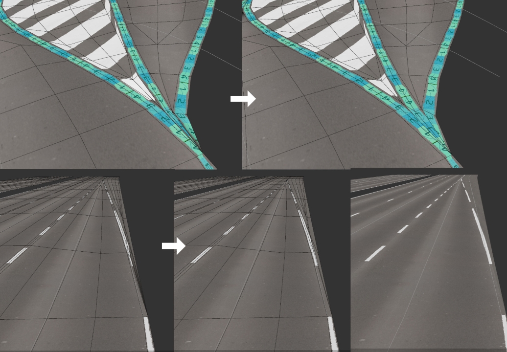
Here is an update of fixing lines intersection, that looks nothing but took an eternity :
 1
1 -
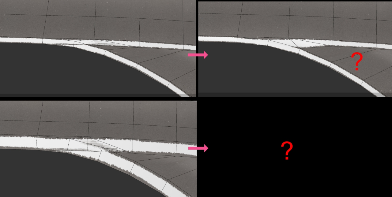
Thanks ! I am working on the last problem, the lines intersections, and see how can I remesh theses polygons without making too much lines intersection calculation :
 0
0 -
UV are done !
 3
3 -
0
-
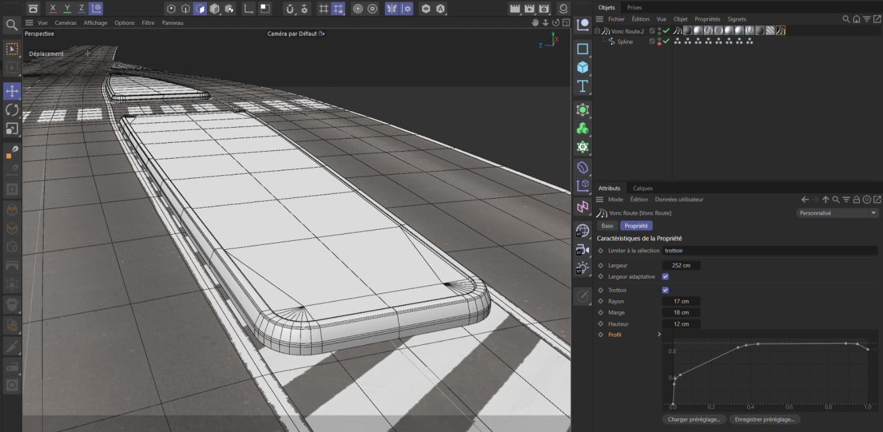
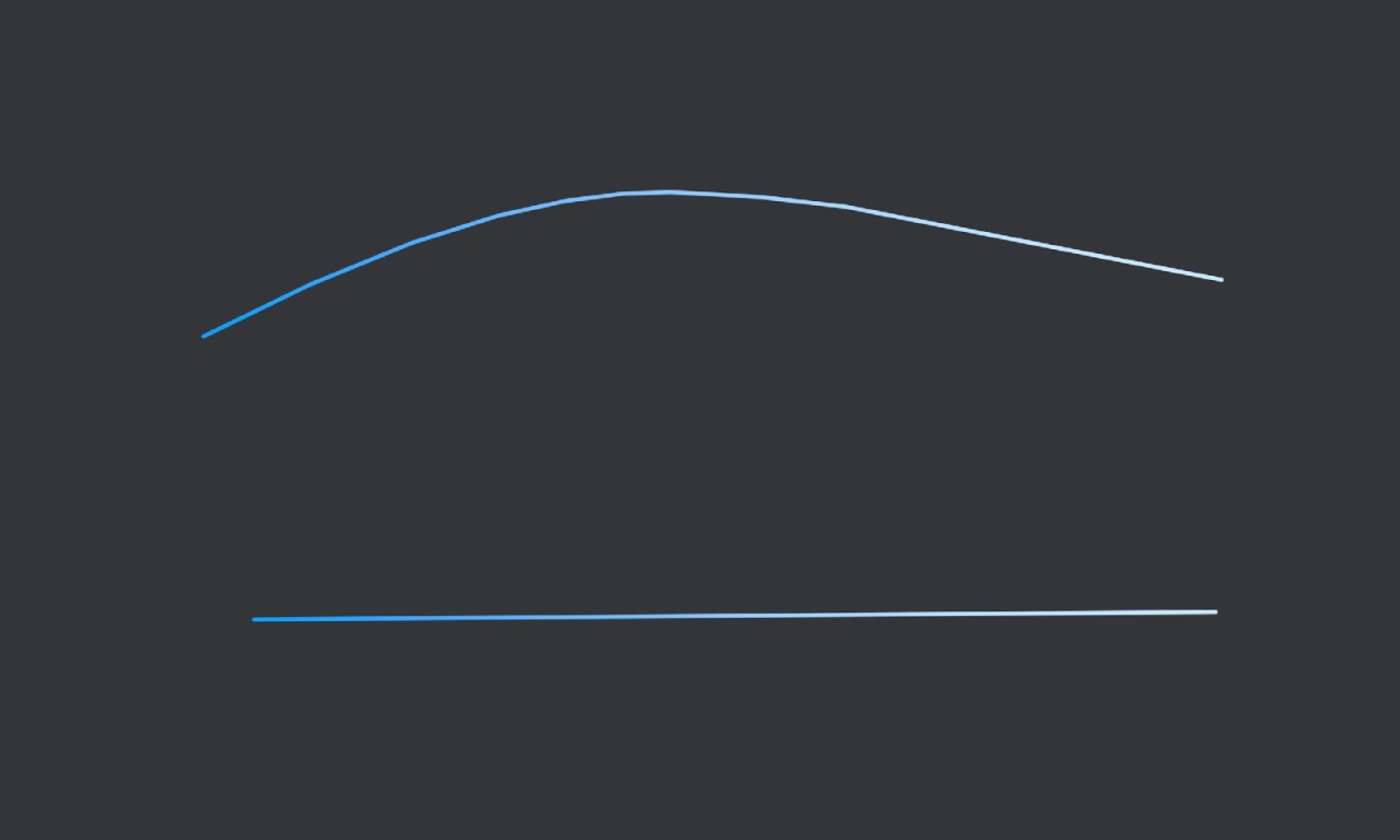
Here is an update with the profile, next will be the UV !
 0
0 -
Hello,
The rotation of the legs is :
rotation = asin(planeUp.y / legLength)Where :
- asin is the arc sine function.
- planeUp.y is the relative Y position of your red plane UP.
- legLength is the length of one leg.
You can make a Xpresso or Python script to do that, without target tag. If you are not familiar with that I can show you an example.
0 -
In addition, to get the grooves of the ball correctly unwraped, you can :
- Make a copy of your football.
- Add a spherify modifer to it and adjust its size, to transform the football to a perfect sphere without changing the mesh structure.
- Do a "Current state to object" of the modified football.
- Make the "Set UV from projection" or "Generate UV Co-ords" from the cubic projection, like you did.
- Then copy the UVW tag of the modified sphere football to your original football mesh and set the UV mode to UVW.
 0
0 -
Hello,
Here is the first step of the central reservation and sidewalk :
 2
2 -
By the way, if you are interested about Bezier curve and spline, here is an interactive demo I made some times ago to understand how it works :
https://code.vonc.fr/courbe-de-bezier
Some fixes with the UV that are now better :
Some fun with weird roads :
 0
0 -
On 10/22/2023 at 5:05 AM, jacobite said:
Looking Really Good CESAR. You must be dreaming of Splines and Points.
Haha, if only you knew how right you are !
Indeed you can replace each texture by what you want !
You are totally right, Dave, for the moment there is no rules to make the roads, we can make any non-sens we want, and we need to specify each evidences.
This will be the next major step, to create a high level more user-frendly, by manipulating objects instead of splines that will automatically create the more logical spline between them, like in simcity games, then if we want to customize, we can convert it to object and edit the spline inside.
I think it will be the more complex because each country seems to have custom rules, the community will be a great help to that !
Indeed, the inclusion with RealTraffic can be possible, I will check that when the plugin will be more advanced.
I also think to make a website after the plugin, to create roads in a web app, without necessarily C4D.
Thanks for your messages, I am back from vacations and continue the work !
Some things to fix, then I will start to make central reservation and sidewalk and after that I will see to make a private alpha release to have some first feedback if some of you will be interested in testing.
2 -
Hello,
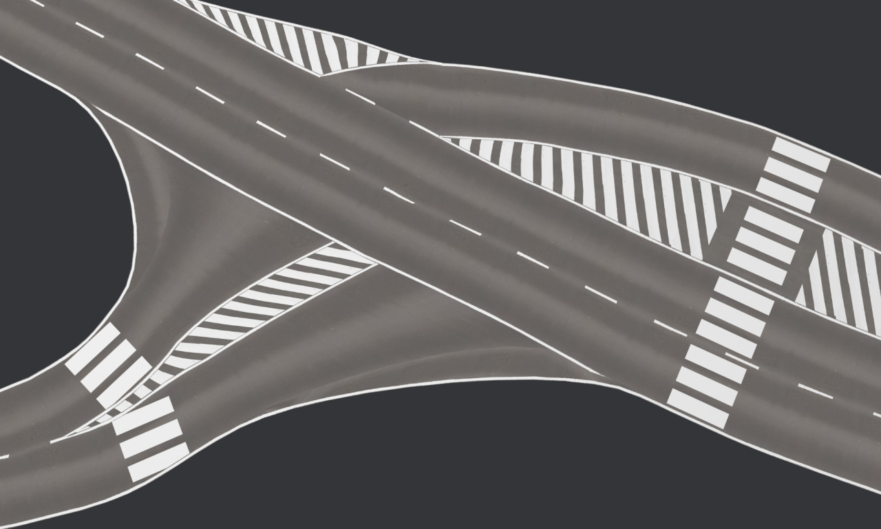
Here is an update with lot of bug fix and the crosswalks, the thing here was to make a planar projection with reference a specific point with its tangent :
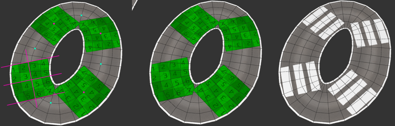 3
3 -
Here is an other test example, I need to make some adjustement with the zebras roads width :
 0
0 -
Yes ! Sidewalks and crosswalks will be the next step. I noticed that the crosswalks don't follow the road curve, so I need to make a planar projection for them. Sidewaks will be a road with extrusion, and by extension we can create central reservation.
I also have to create some tags to set some properties of the roads, like its width, for now it's a default value for all the roads.
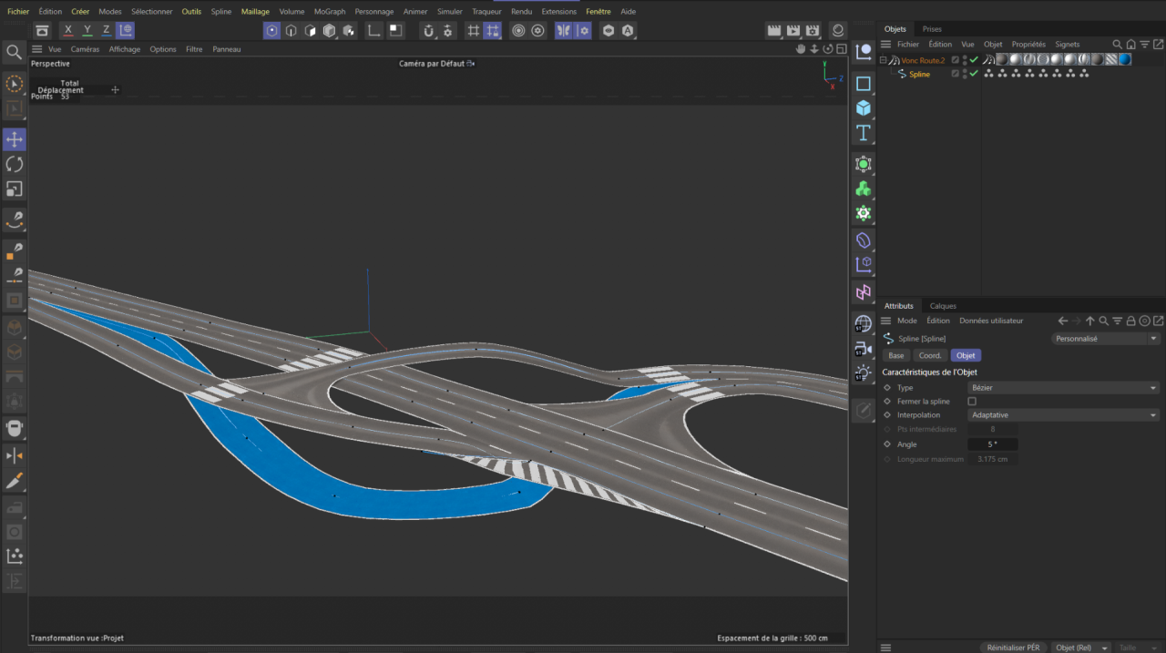
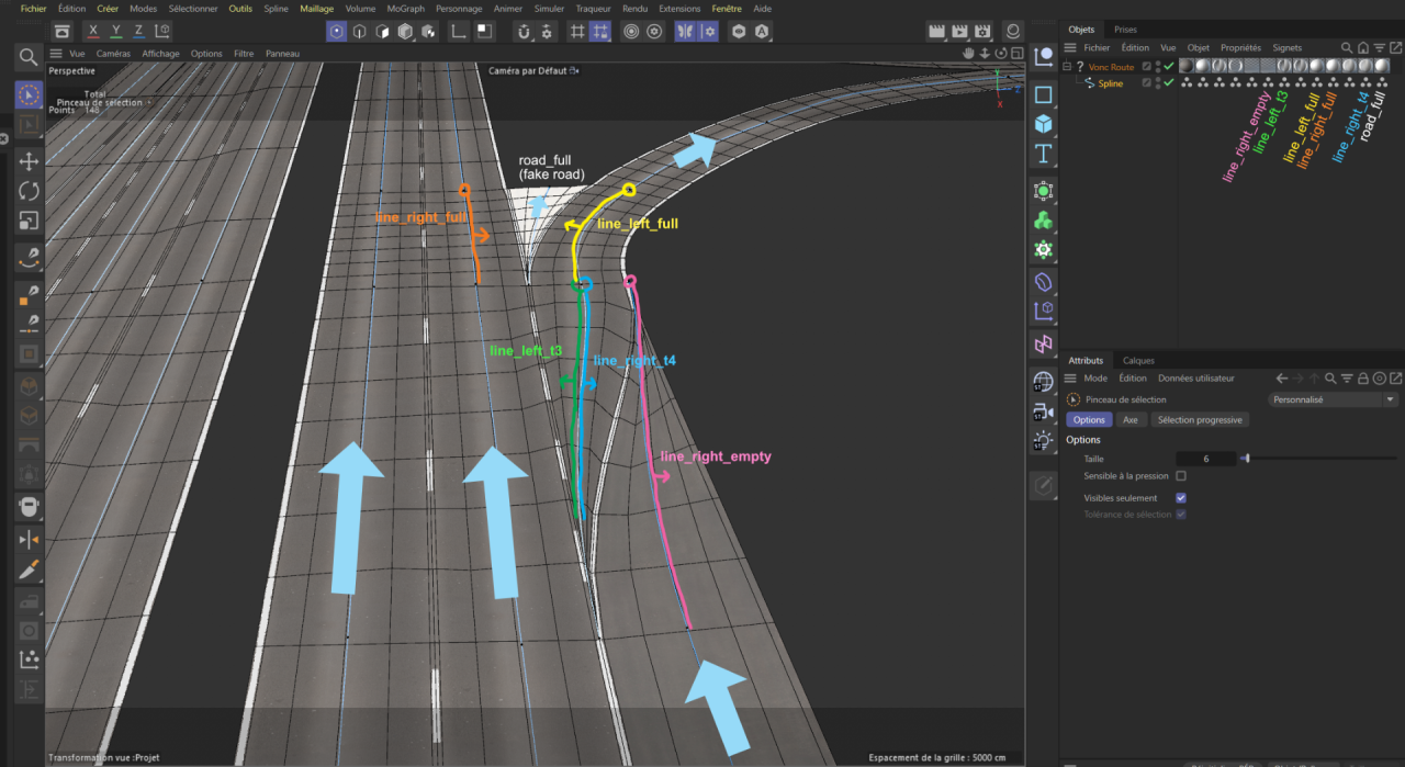
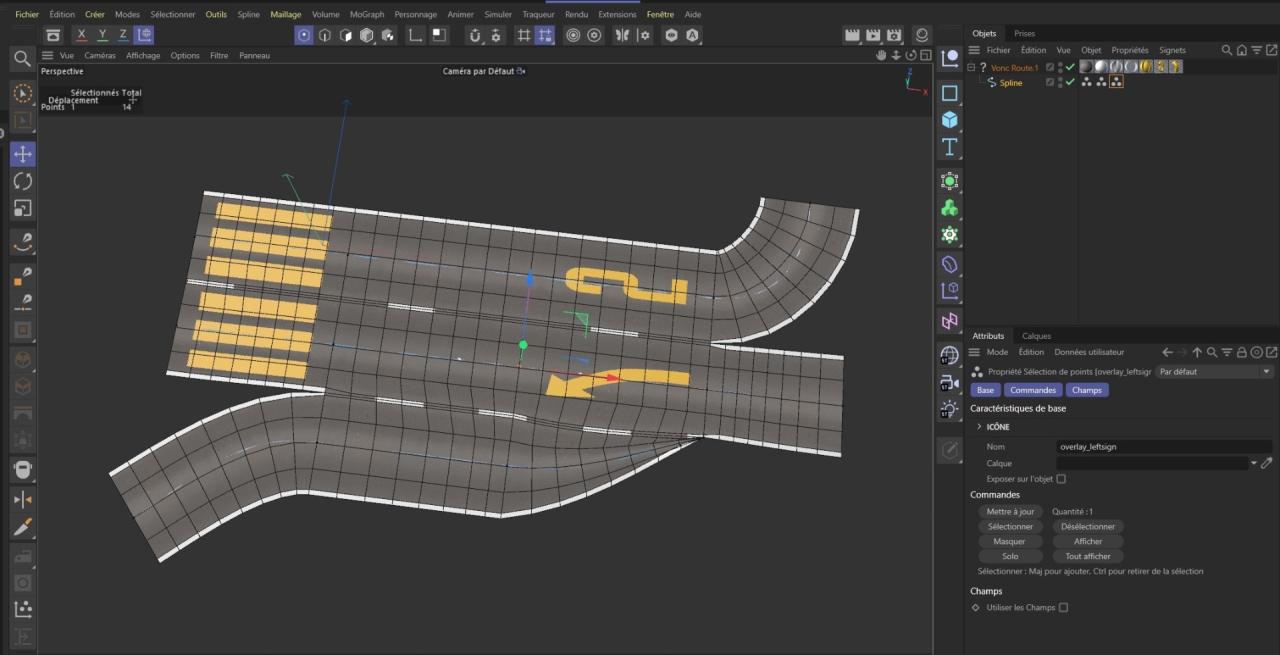
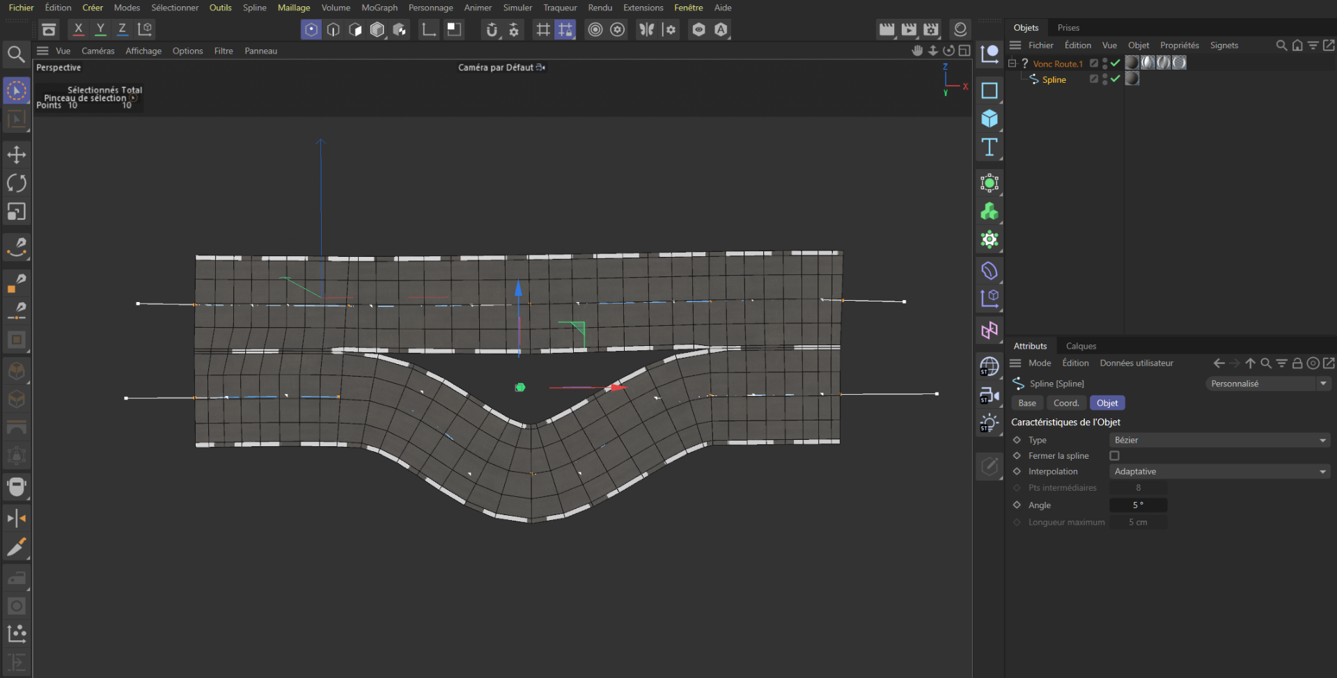
I think I will make generator of preset splines, or an other way to configure the road properties, actually it looks like this picture, the splines points have to be in a very specific positions, and the points selection may be a bit complex to use. An overlay userfriendly may be the solution but I am not very good on UX/UI.
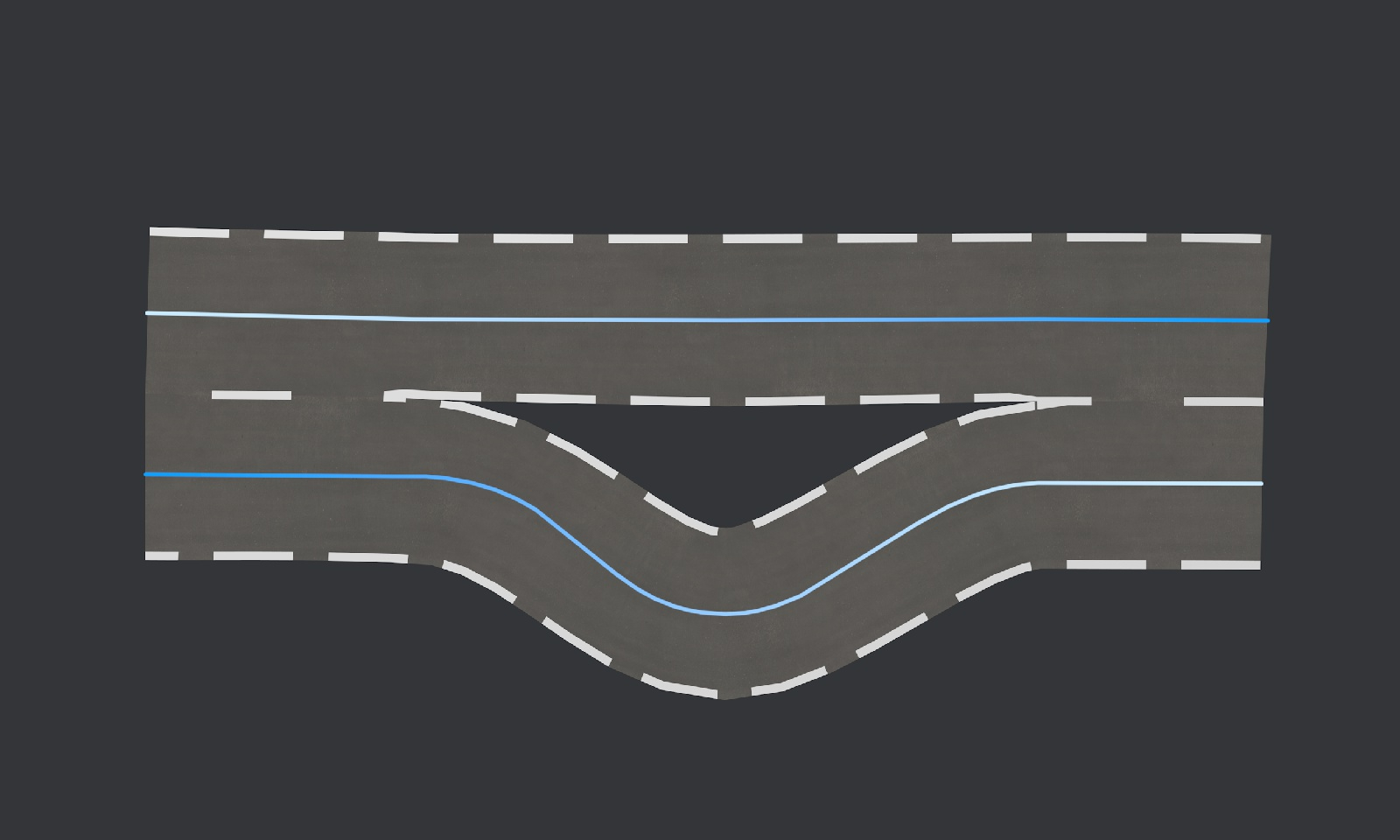
How we actually customize the lines : (by default, border lines are full, lines between two roads are dotted)
I will reproduce some other real life example to see what is missing.
1 -
Hello,
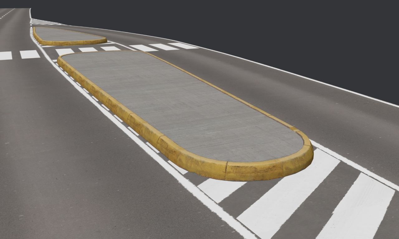
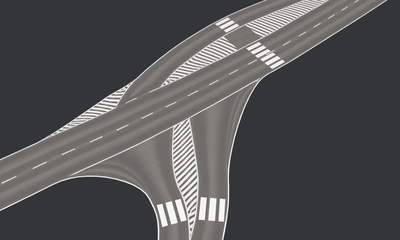
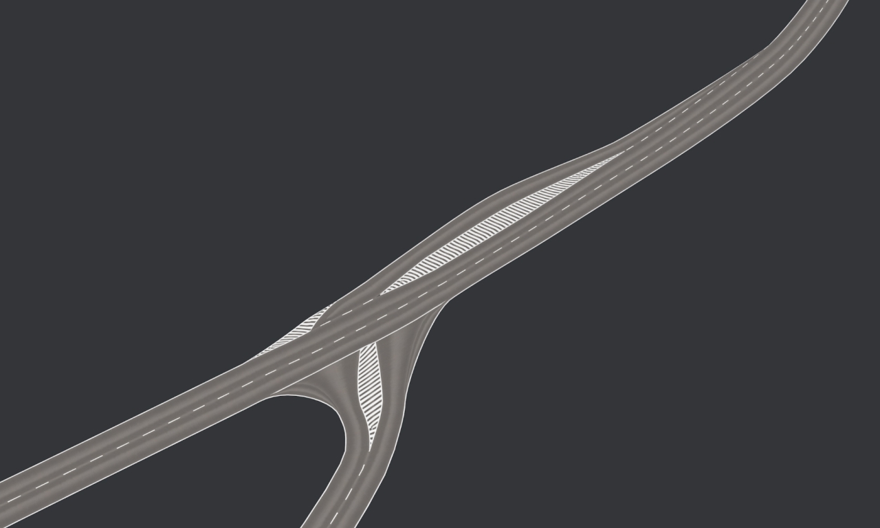
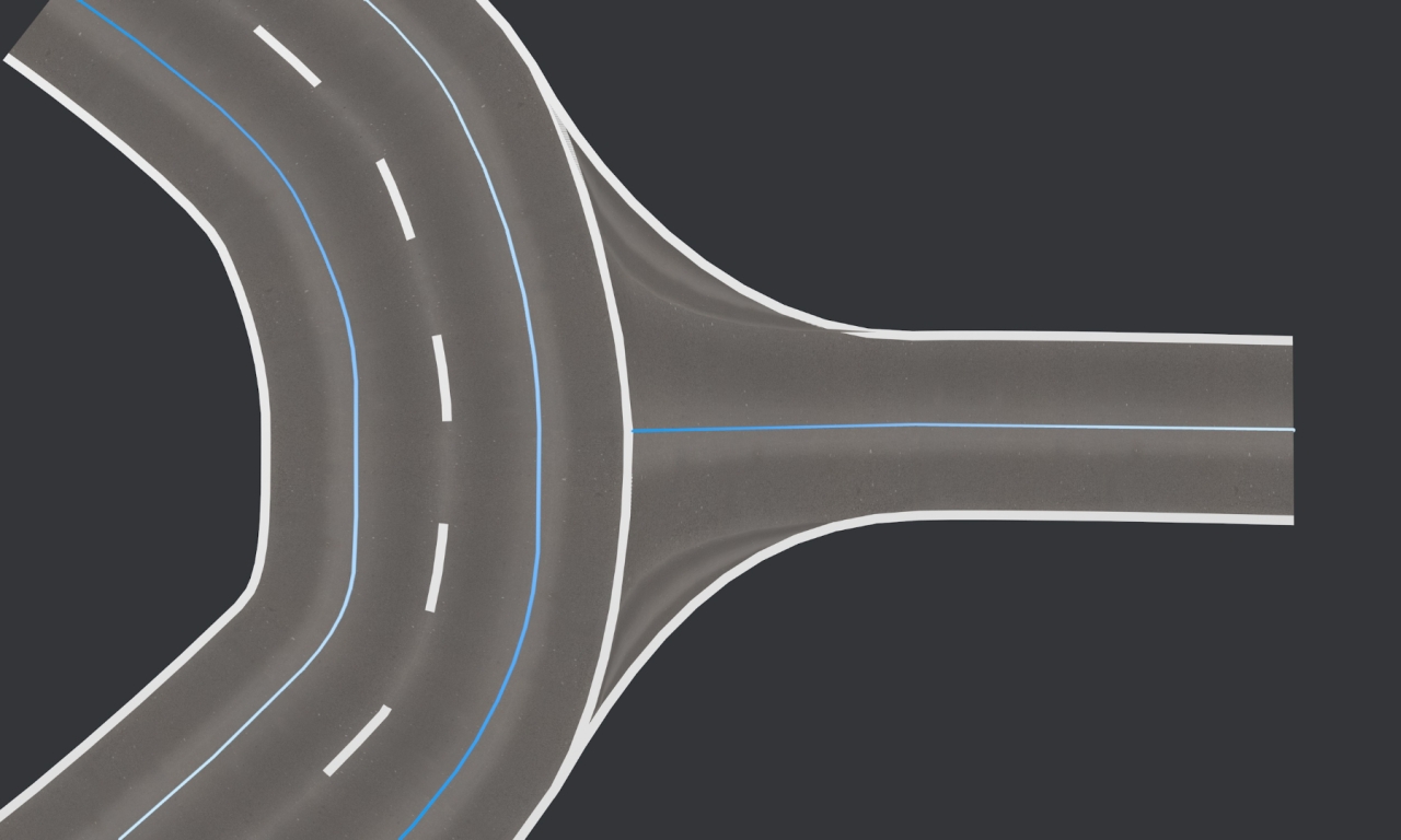
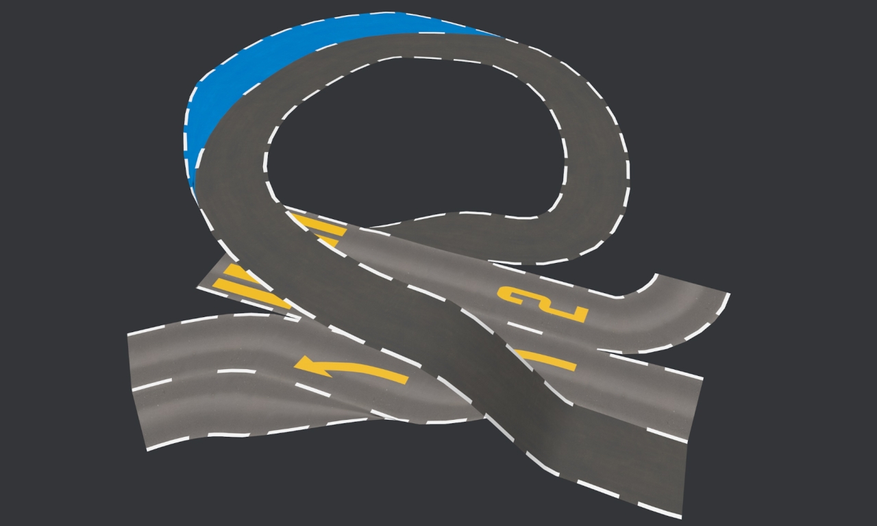
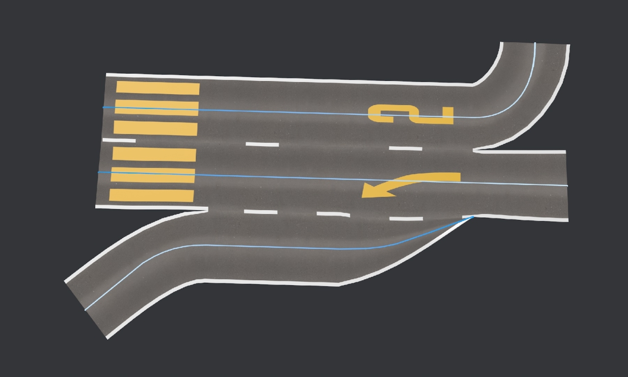
Lot of work has been done, here is a complete example with a highway ramp, inspired by this photo :
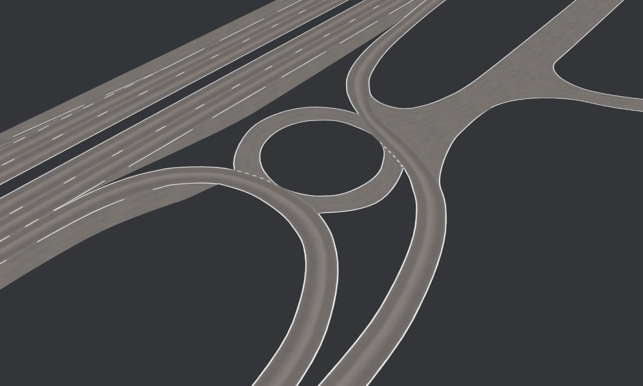
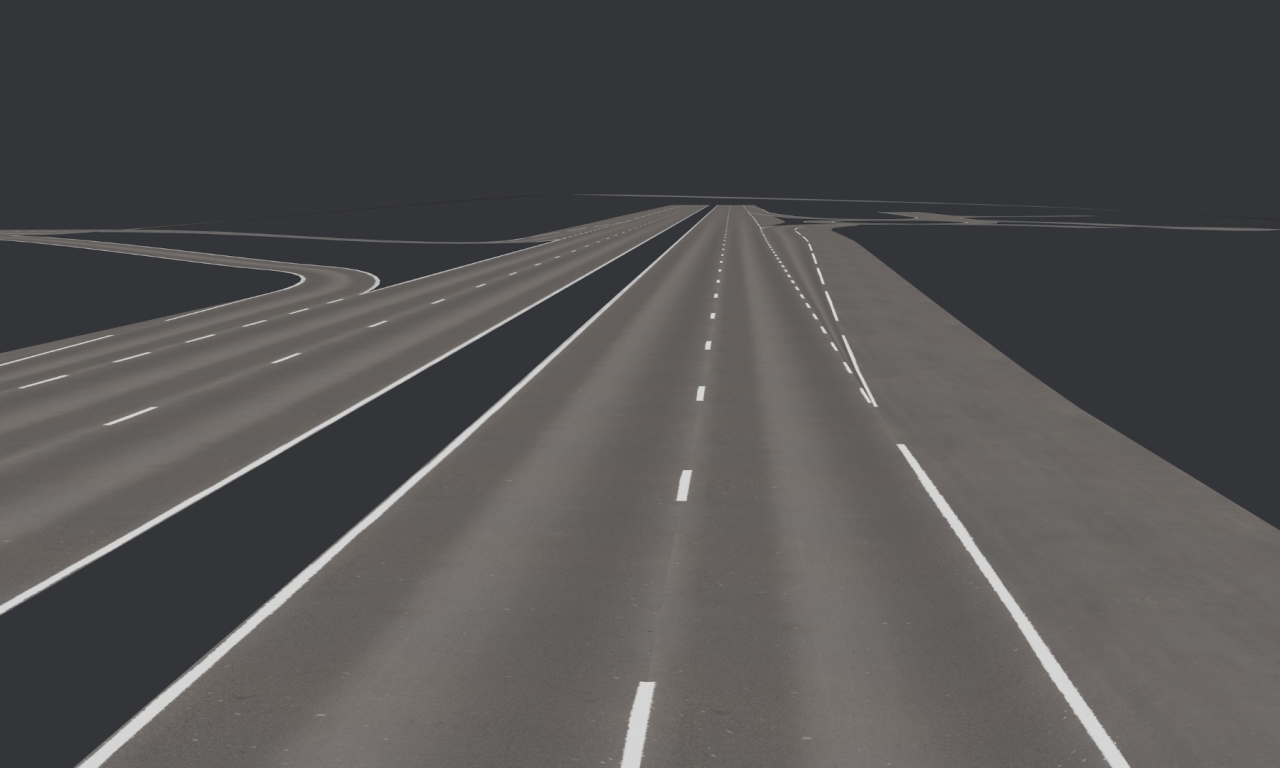
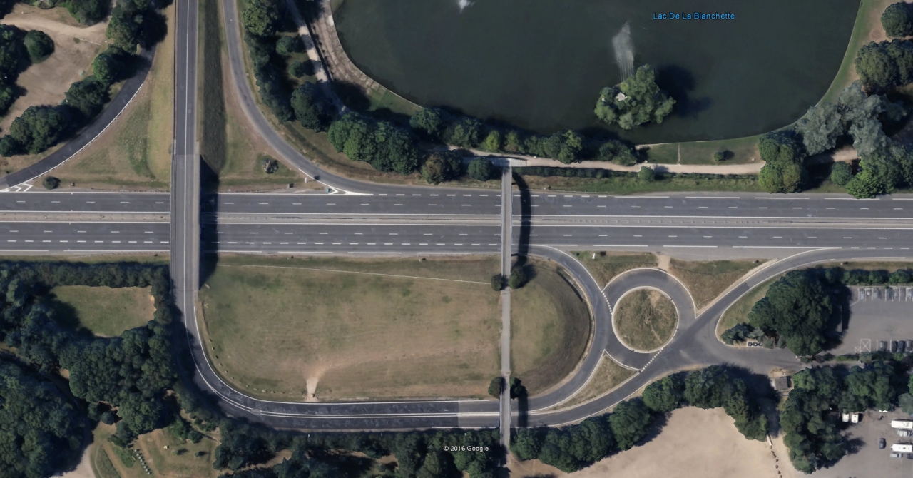 4
4 -
On 8/2/2023 at 10:24 AM, zeden said:
Yes. Stuff like that. Amazing.
Very nice indeed !
I am pretty sure that we can do the same in C4D since Bodypaint exists, by painting alpha texture of a multi layers shader.
The textures principle did not evoluate indeed, I think it's because of the problem of the texture itself, which is simply a 2D image, so we have to unwrap it on a 3d model and I don't see how to change it.
Point vertex color become more populated since graphic cards can handle a huge amount of vertices with no problem, more vertices we have, more detail we can add and can replace a texture in some conditions, it's the basis of the shader computation and it's used for always in photogrammetry and laser scanning and radiography.
A revolution would be kind of 3D textures scanned from the environment, the texture will be a cube instead of a square, with depth informations, and be applied like procedural C4D shader (and its wonderfull wood shader), so no unwrap nor UVs, that would be very nice !
I imagine the 3D texture can be a very complex procedural texture, with algorithms stored instead of pixels (hey but the JPG compression isn't an algorithm based on 8 pixels squares... ?), or it can be a huge box of voxels, or both ?
I don't think that a 3D texture could be scanned from the reality (because we can't see through walls), but I am sure that an IA could extrapolate a 2D texture into a 3D one, the 3D texture will be a multiple layers of 2D textures with logical continuity in depth, imagine a 3D brick texture that looks like a box of 3 cubic meters full of bricks.
Some compressions algo like a "3D JPEG" can be invented to redure the texture weight.
I hope it's not too messy, it was just an idea.
1 -
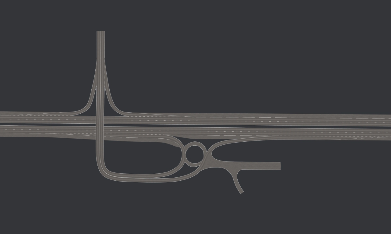
Sorry for the double post, but I am so glad to show you the first test of a roundabout !
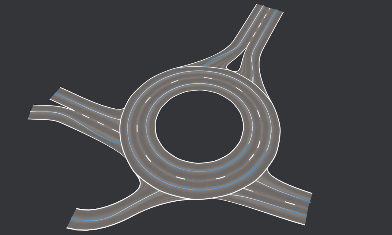 2
2 -
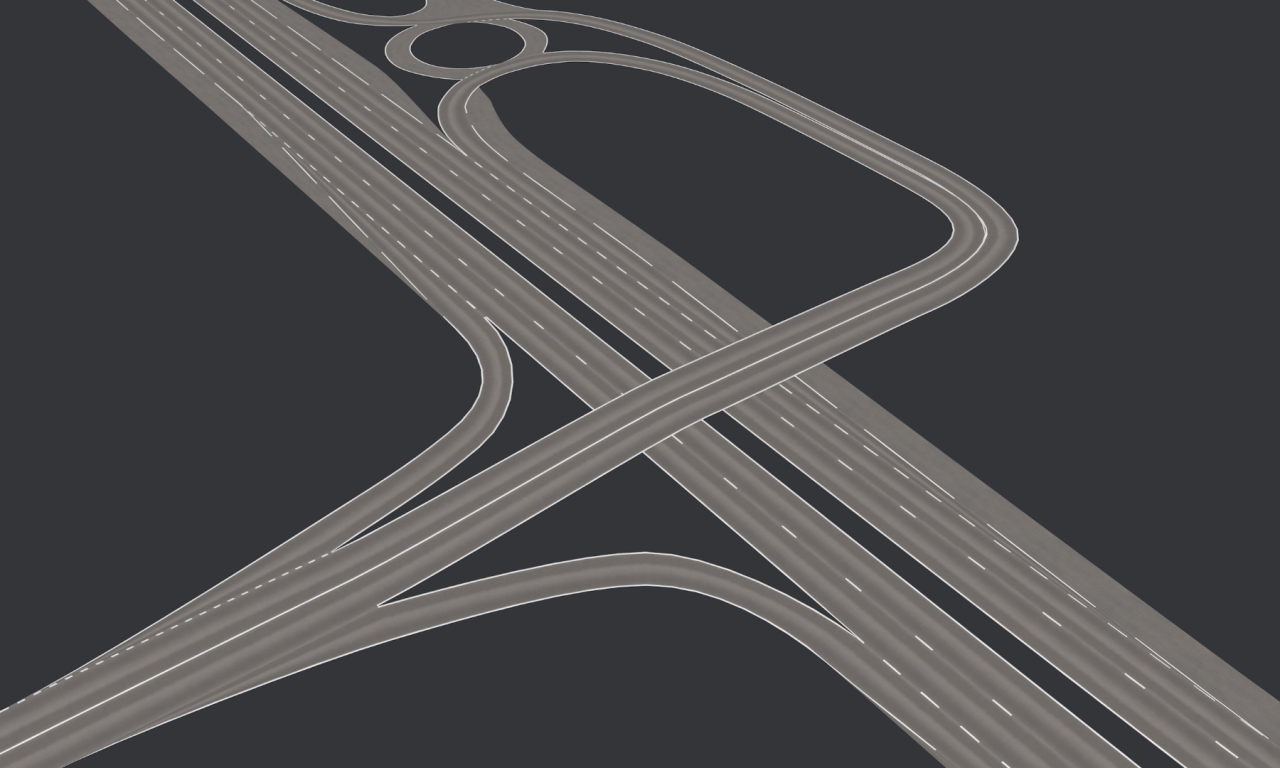
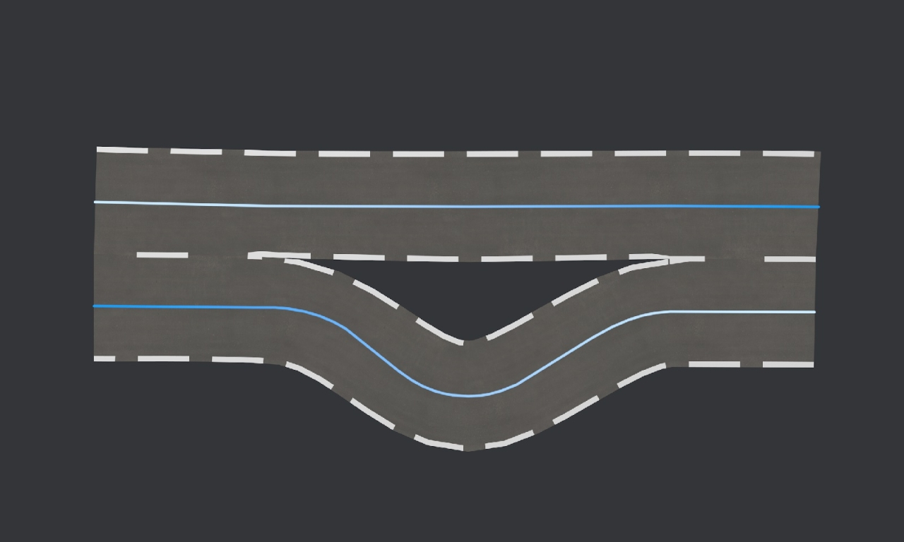
Here is an update with the intersection test, when a spline comes to an other one :
There is some work to do with the lines and the UV, note that the subdivision can be adjusted :
 2
2 -
Thanks, for sure, Kweso, if the Y position changes, I don't join the roads.
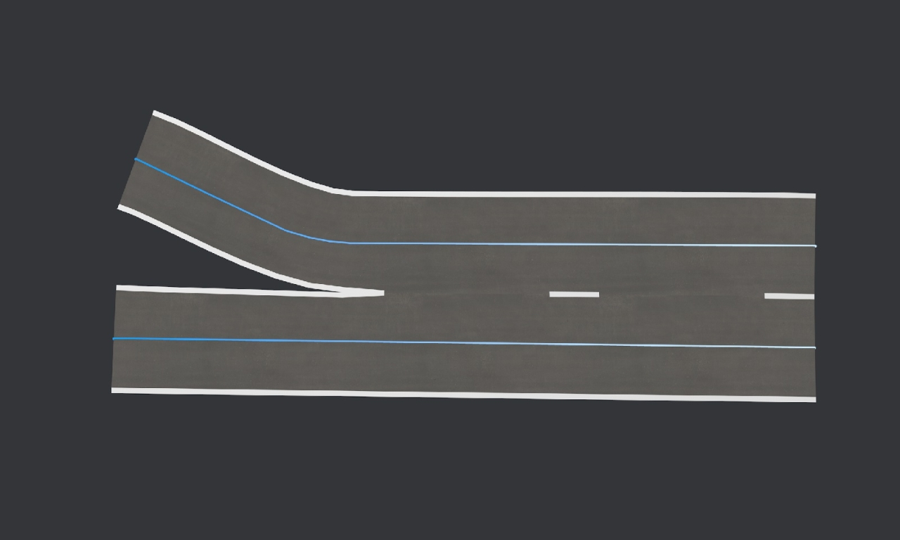
Here is an update with the road material assignment (works line the decals with points selection), and a Y offset example :
The melt road has been improved, I simply keep the bezier tangents of the target road to keep it straight :
 0
0 -
Here is the overlay feature and the first junction ; if a spline point is very close to an other one and its previous point is close enough to be a lane, the very close point will melt into the road (still some work to do with the bezier melting) :
If we add a point selection to the spline and a material with its name as a restriction selection, the decal will be on the segment previous the selected spline point :
 1
1 -
13 hours ago, bezo said:
Nice work César, do you plan also horizontal signs for example for airport runway?
...and maybe custom road textures
Thanks, airport runway is indeed an excellent idea !
I am implementing overlay textures for horizontal sign and will post examples soon.
Road and lines textures can be changed as well.
1 -
Hello,
I am currently interested in creating roads and intersections, and I am making a new plugin to manage that.
I realized that there were a good number of possibilities for intersections, and I would like to make the most flexible plugin so that it could adapt to any situation
Here is my progress and the current features, I post on a WIP because I think there will be lots of special cases that I haven't thought of and I would like to be able to manage them.
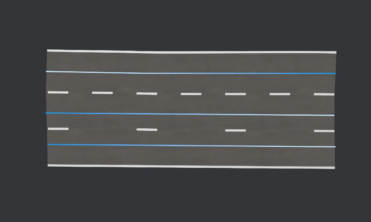
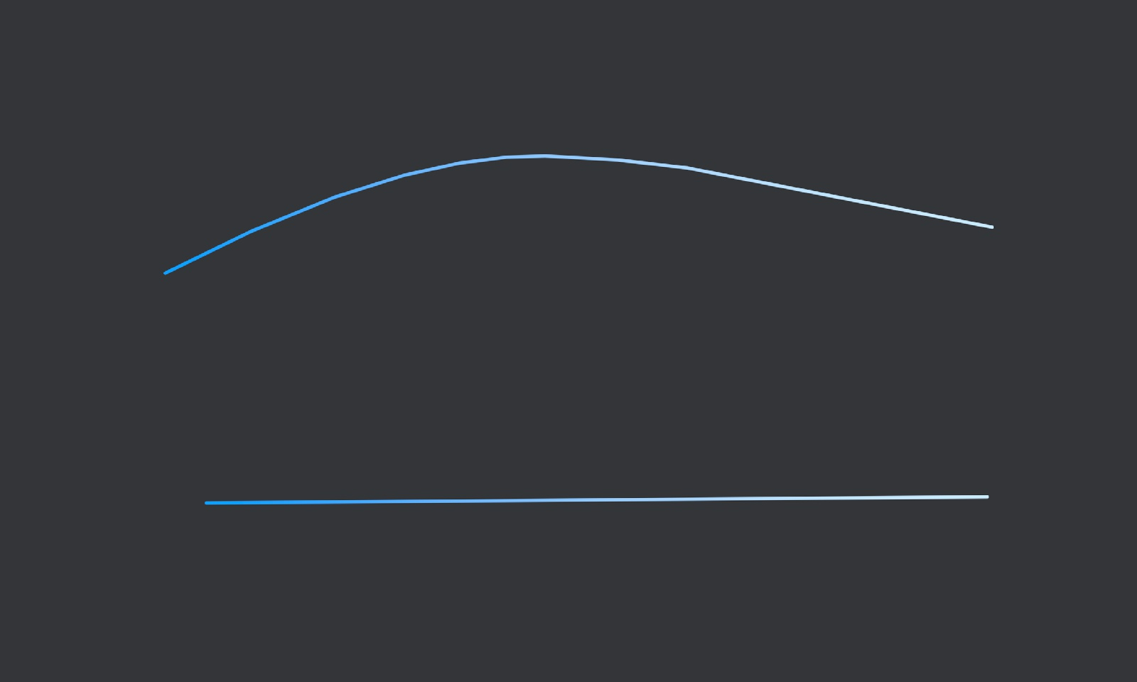
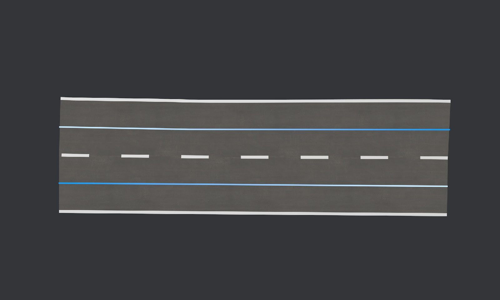
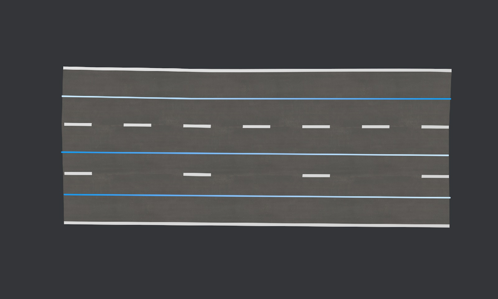
First, the road are defined by splines :
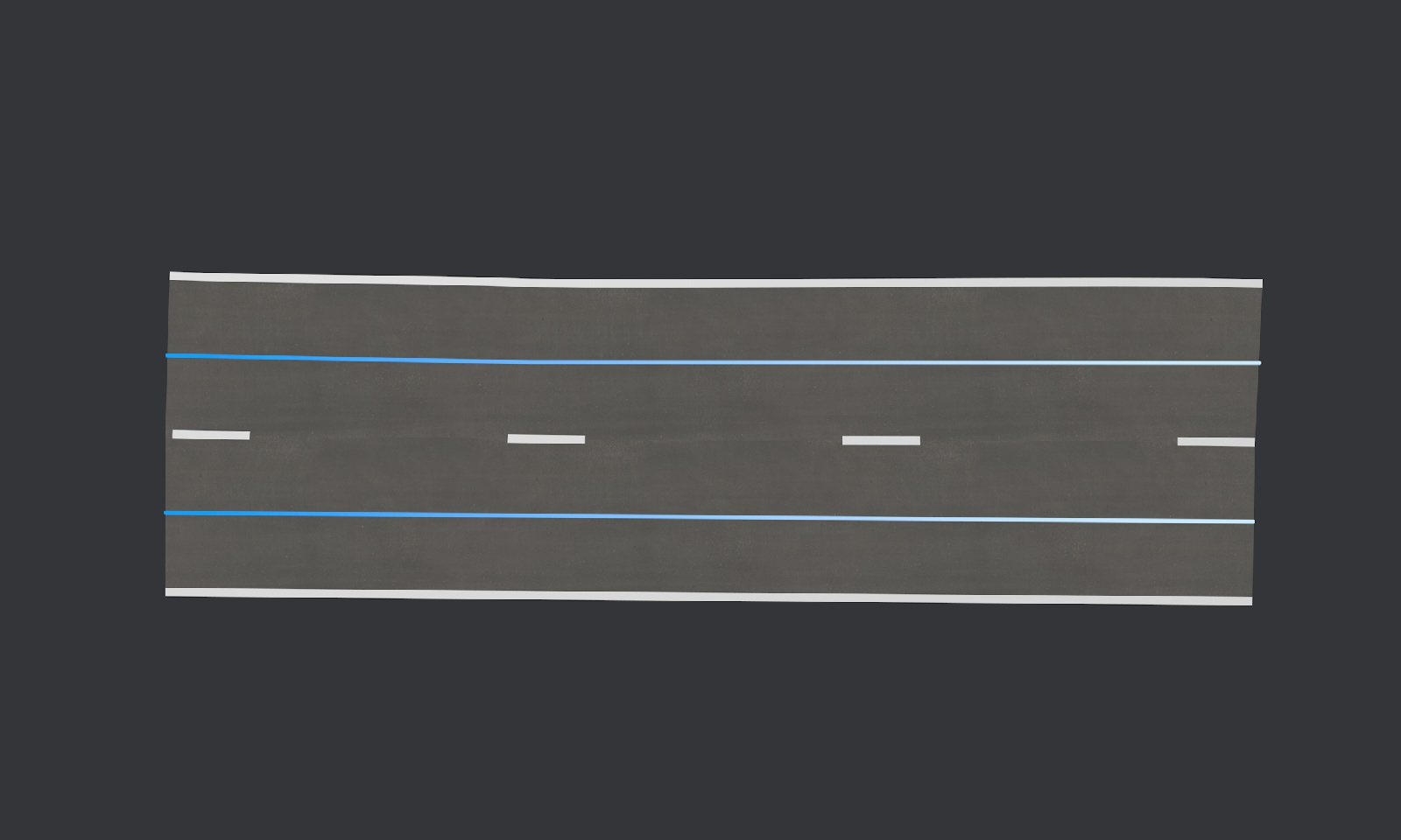
The plugin generate textured road polygons from the splines. It also add a line on both sides of the road :

If two points of the splines are close enough, they will be magnetized :

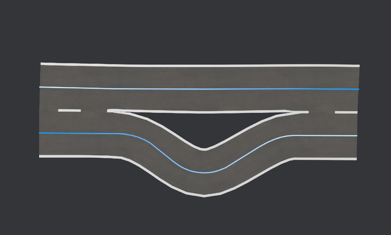
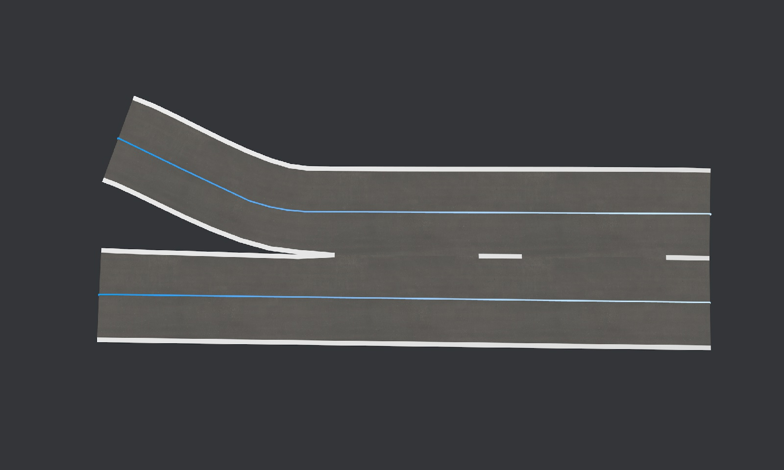
If two or more spline points are close enough, the splines are unite into one road of two lanes, the material of the line changes :

If the direction of the splines are different, the material of the line changes (defined by the user) :

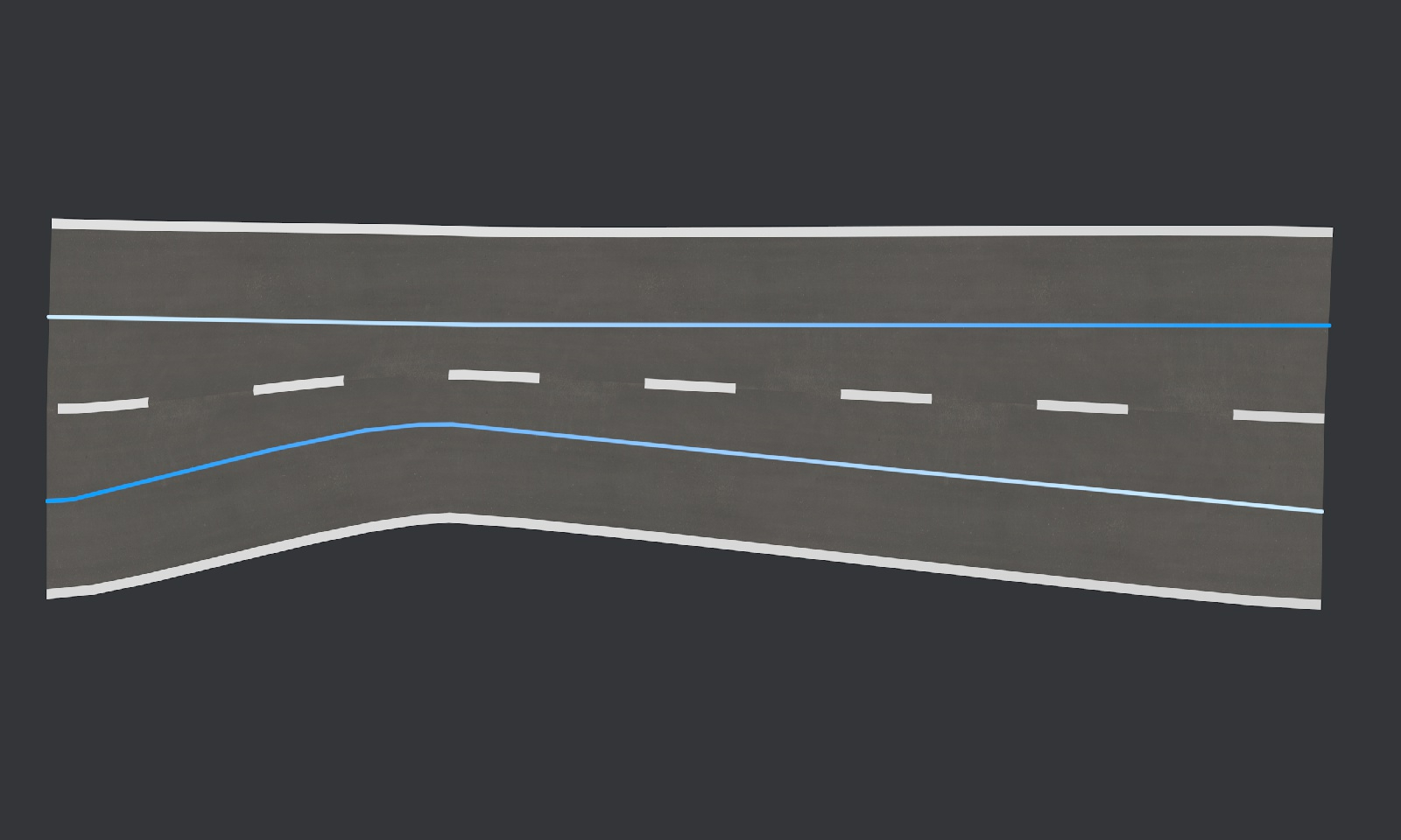
We can add many lines in any directions :
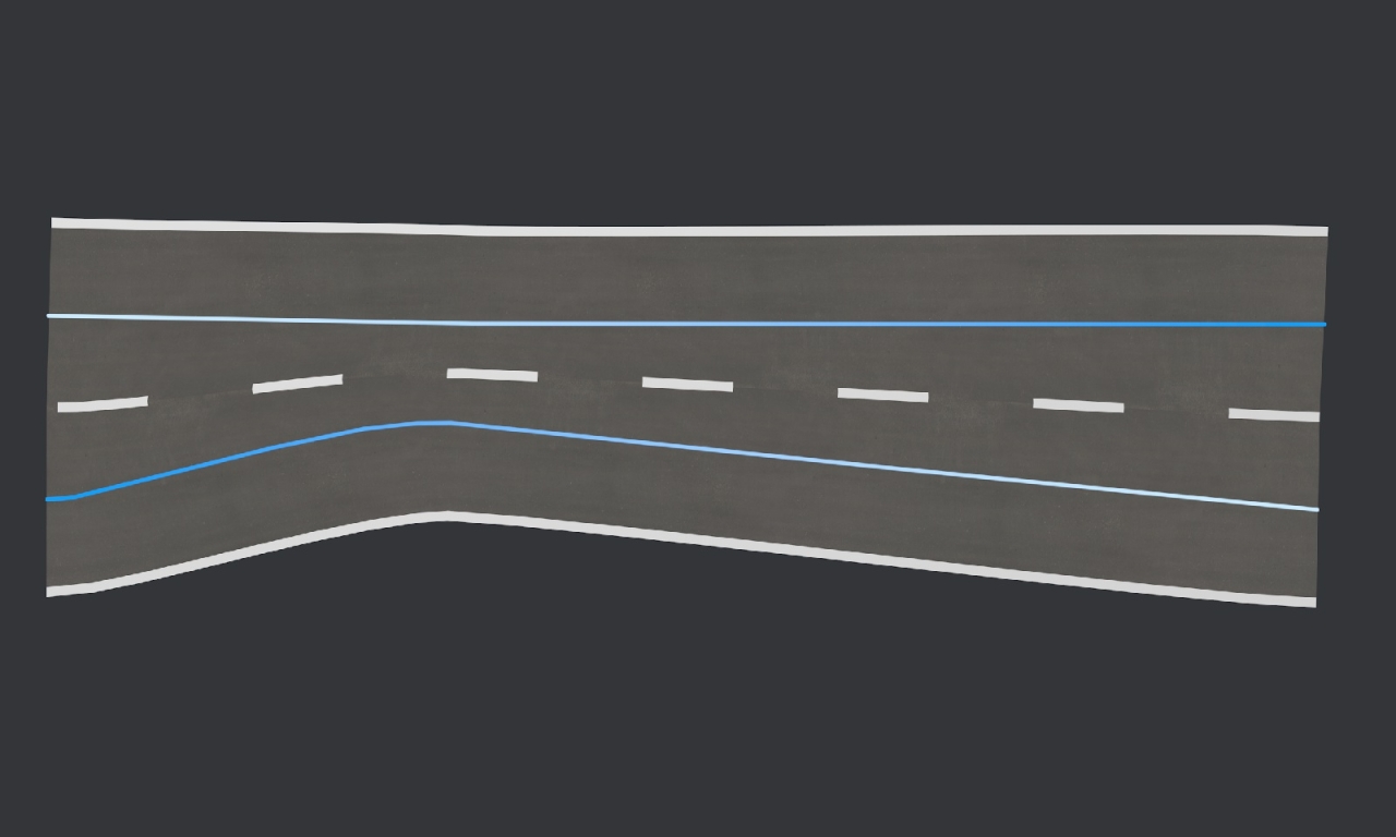
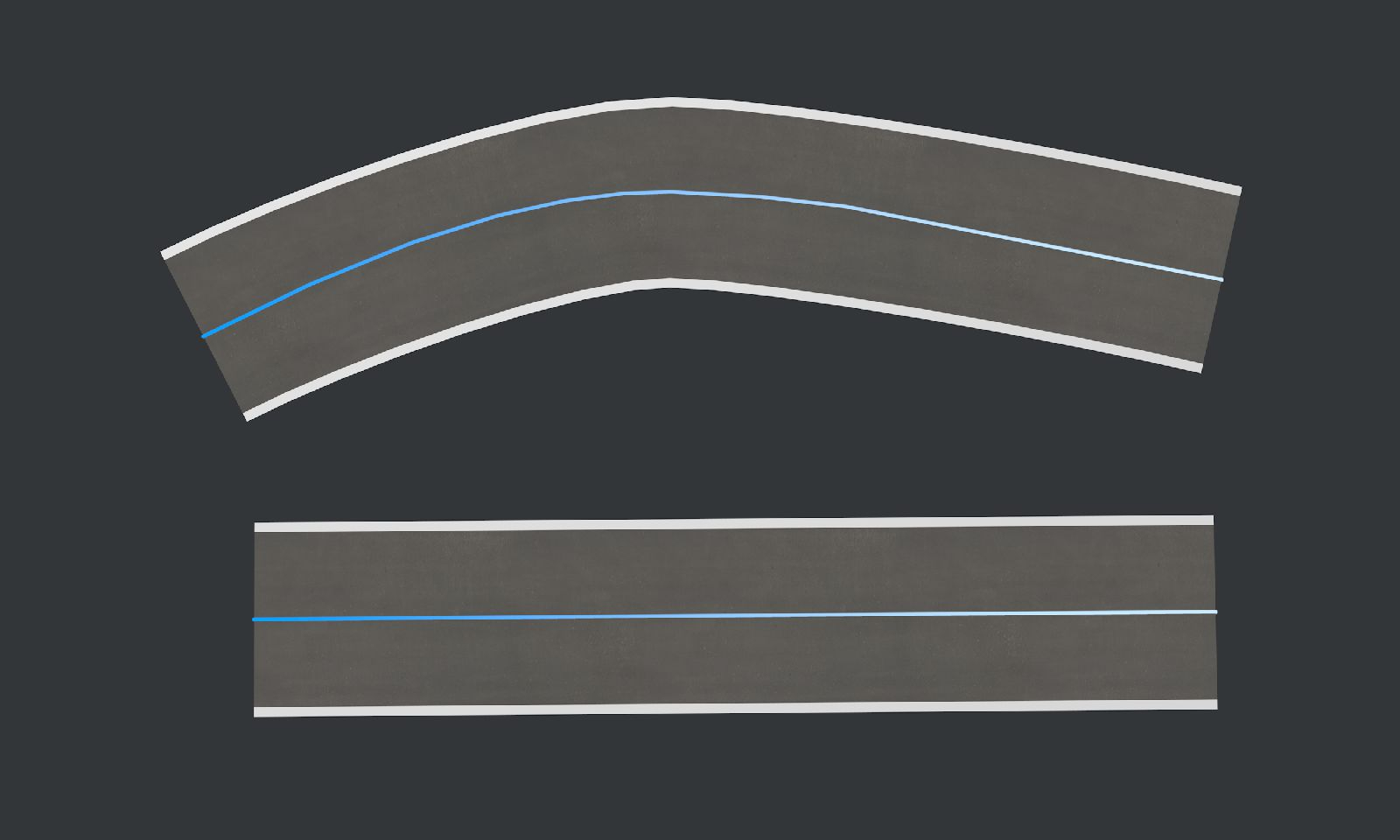
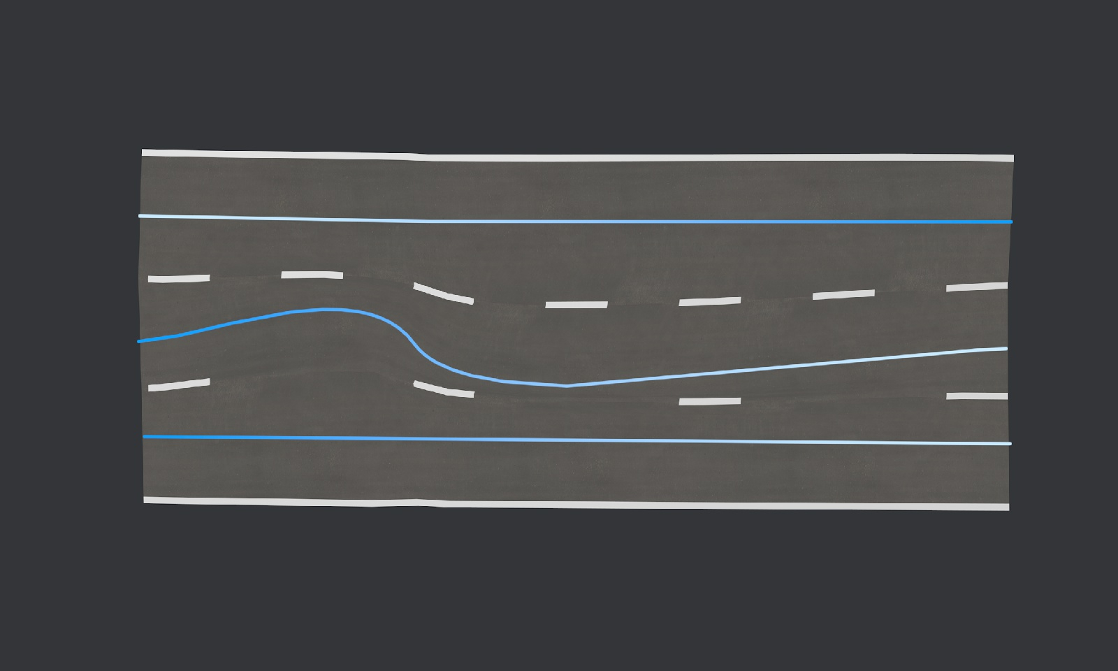
A twist in the spline affect the road path :
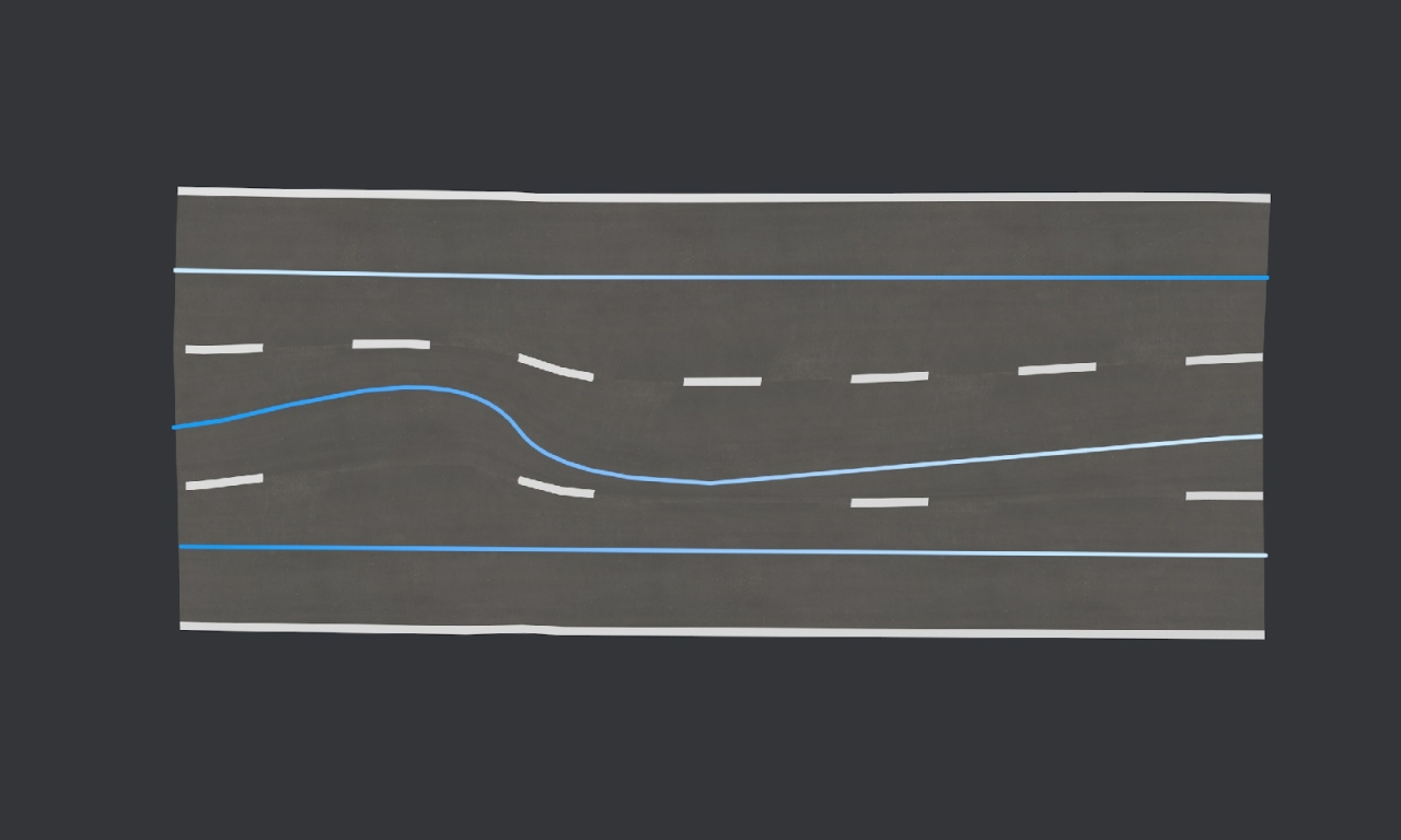
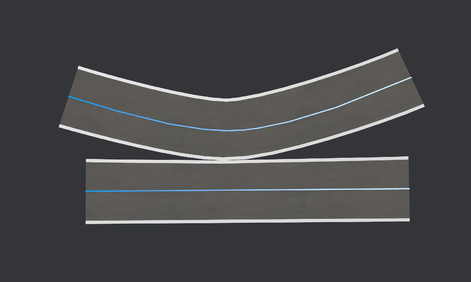
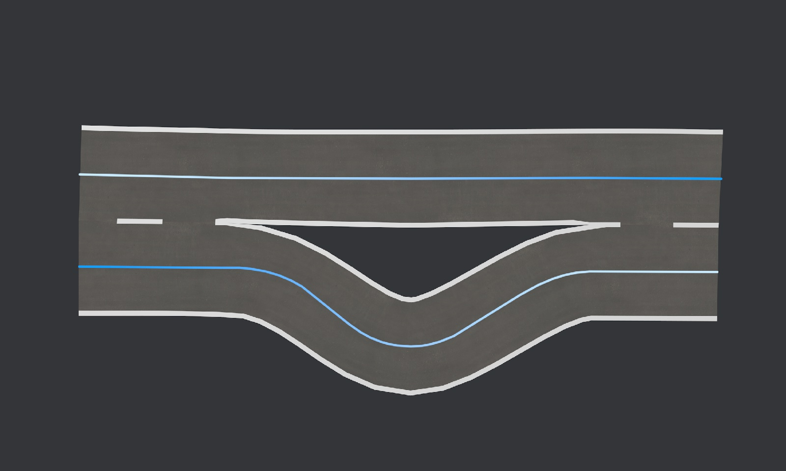
We can disconnect and reconnect the lanes by moving the spline points :
The line material will try to match as possible (still work to do here) :
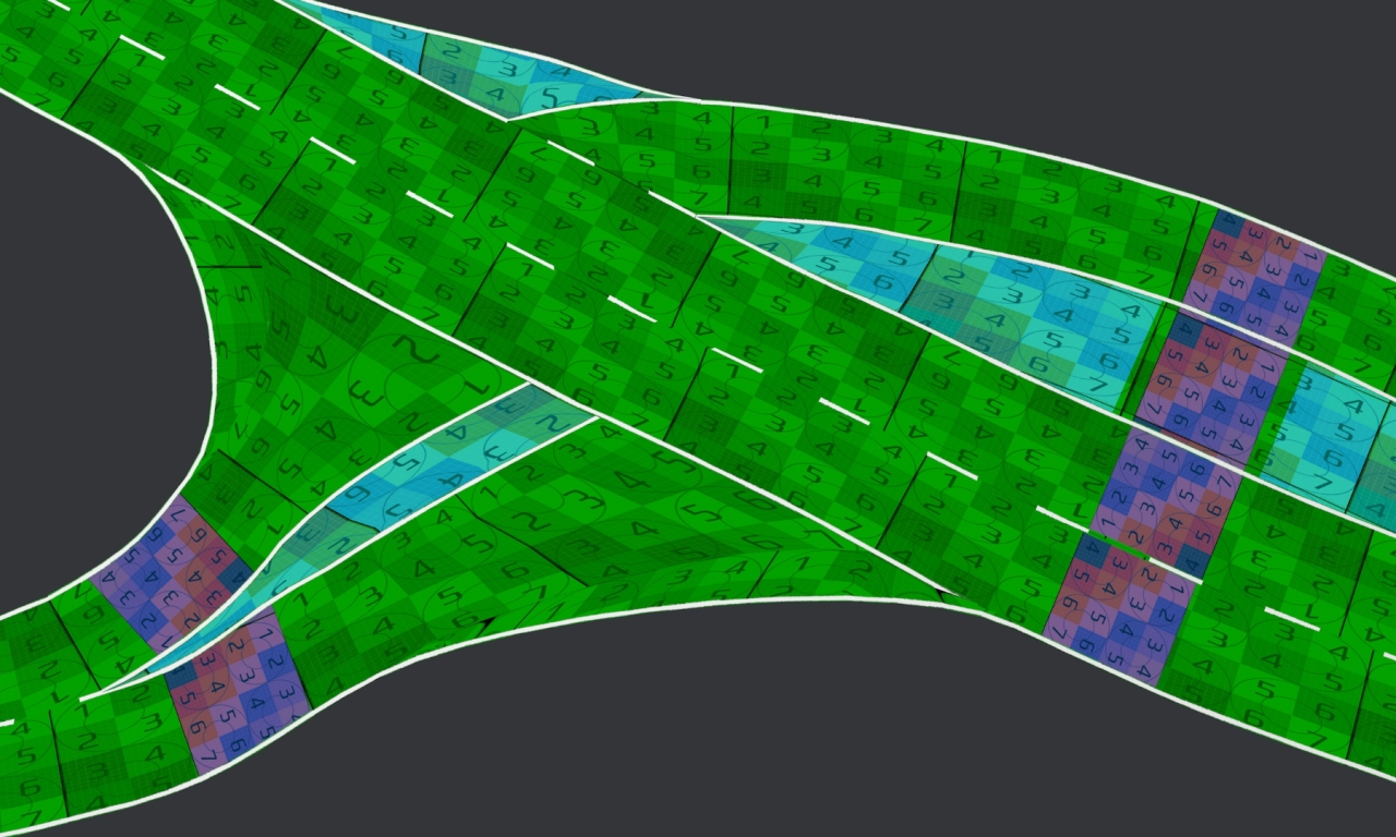
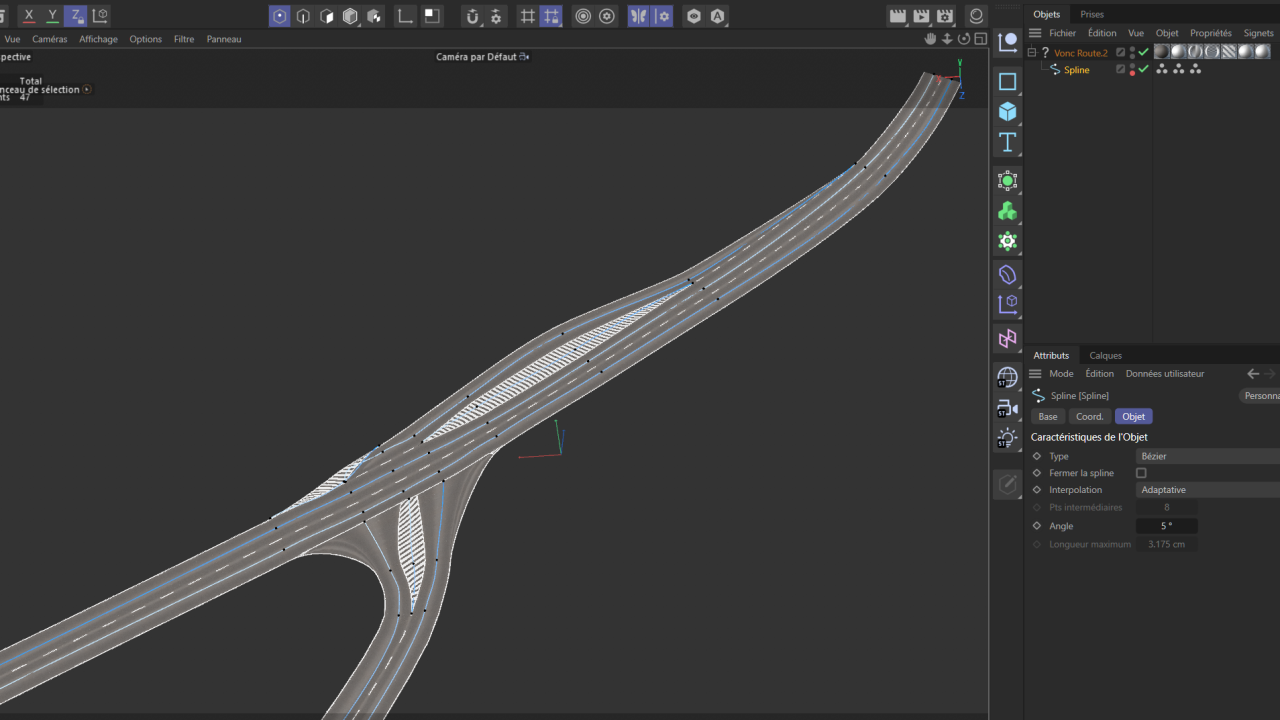
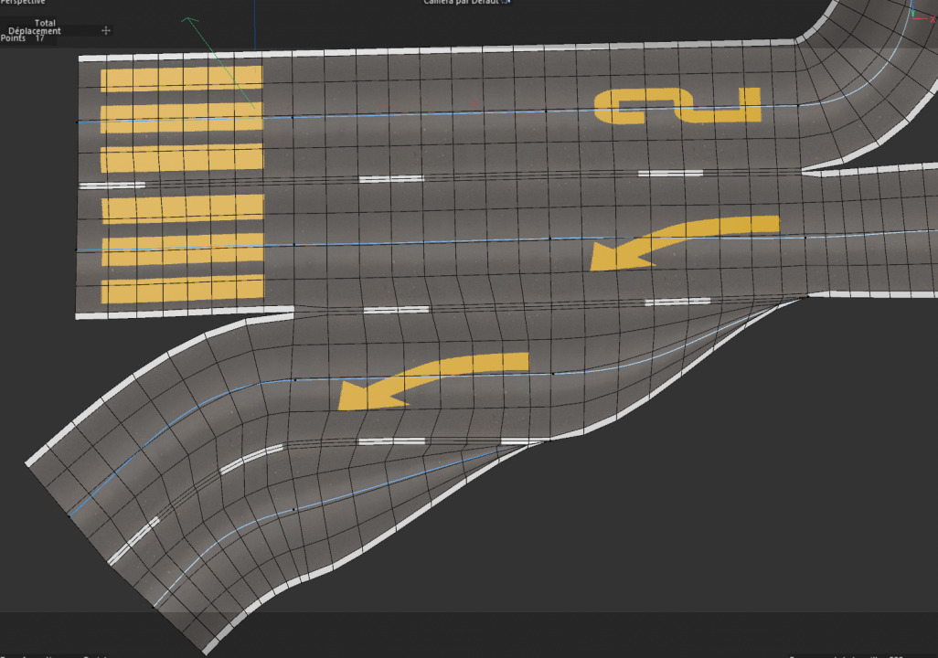
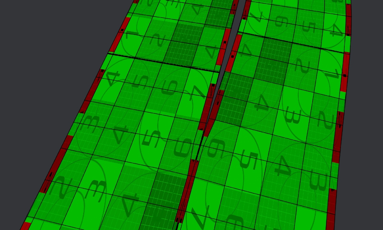
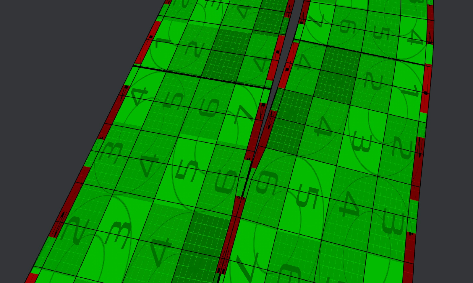
A preview oif the setup and wireframe in C4D :

The road is a object with two UVW tags and some polygons selections to dissociate the lines :
The next step will be the intersections.
For the moment I develop it as a C4D plugin but I think it will also be an online tool with some exports options.
I'm based on European roads for the moment, but I would like to look at signs from other countries to see the differences.
Looking up for your comments and suggestions !
8


Road Generator (WIP)
in Plugins
Posted
@Vozzz Yes, we can change the lanes width
We can also change the lane width at a specific point (to make wider in curves for example), but I did not desin the UI for this for now.
I am currently working on the top level user interface to make it easy to use, and also the WebGL implementation to use the tool online. After that the alpha can be released.
UI are so long to do !