


Jaee
-
Posts
309 -
Joined
-
Last visited
Content Type
Profiles
Blogs
Forums
Gallery
Pipeline Tools
3D Wiki
Plugin List
Store
Downloads
Videos
Posts posted by Jaee
-
-
Thank you! It was so helpful!
0 -
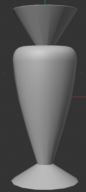
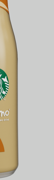
I'm trying to model this shape in Cinema 4D. Can you help me? I tried using the Lathe Object in this way, but when viewed from the front, the center heart-shaped part didn't come out in the same form as the reference image. So, is it possible to model the bottom as a flat, circular base like a glass, while maintaining the shapes of the center and top parts to resemble the reference image?

 0
0 -
1 hour ago, jbatista said:
Its a modelling issue since its a hardsurface object with subdiv. Try this:
by the way, you forgot the tex file.

cheers
It still has the same issue
 0
0 -
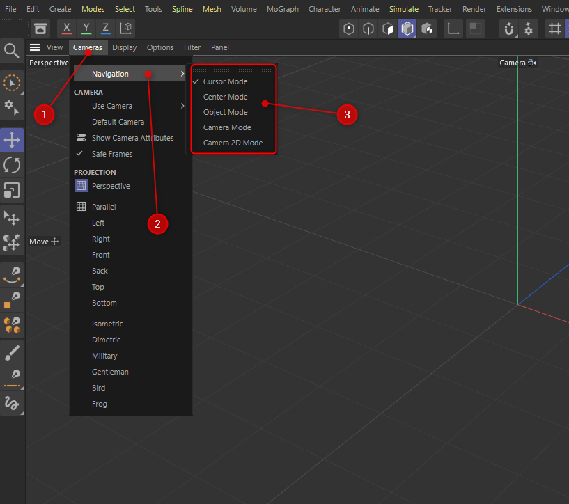
In Cinema 4D, when I zoom in while working on UVs in the Texture UV Editor window in UV Edit mode, the perspective view and UV window screens freeze. All other buttons work, but the screens freeze. Do you know why this is happening? I have to keep shutting down and restarting Cinema 4D.
0 -
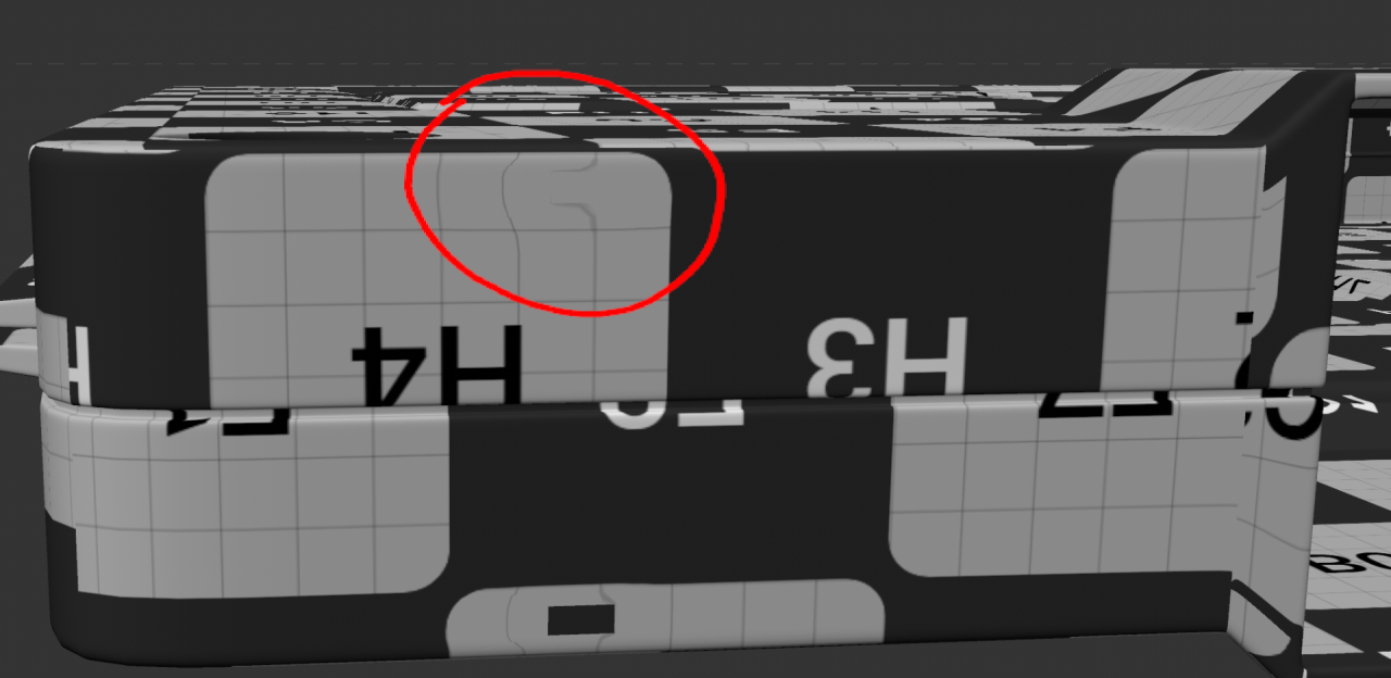
I'm texturing UVs, and there are distortions in various places. Is there an issue with the UV unwrapping, or is it a modeling problem?
I am attaching the working file.

 0
0 -
On 9/8/2023 at 3:15 PM, Jeff H1 said:
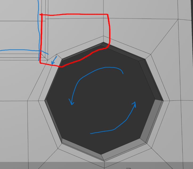
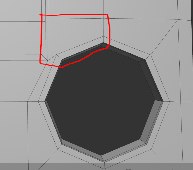
Could you select the edges that make up the circle along with their supporting edges and rotate them counter clockwise a bit to have that corner align a bit better? Then it looks like in your snapshot you haven't added the supporting edges on the square yet.. I drew them in blue. you may be able to use those to connect and eventually remove that 5 sided poly? I don't know if the non-planar polys will matter that much when they're subdivided. You could select their points and scale them to make the poly flat probably.
Thank you so much, Jeff! It is so helpful!
0 -
On 9/3/2023 at 3:19 PM, Cerbera said:
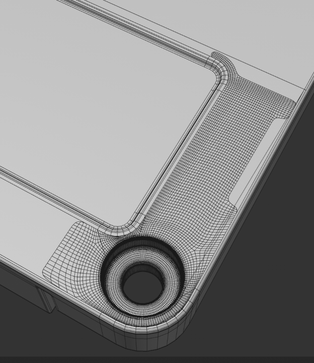
First of all - are you modelling the outside only or doing the inside as well ? If it's the latter then you should start with the inside, which better governs the polys you actually need.
What you have done here is fine but probably way too high poly - for example that hole on the corner should be able to be described with an 8 or 12 sided disc.
By starting so high poly you condemn yourself to wrangling that increased amount of them all the way across the model, rather than only having poly density you require.
CBR
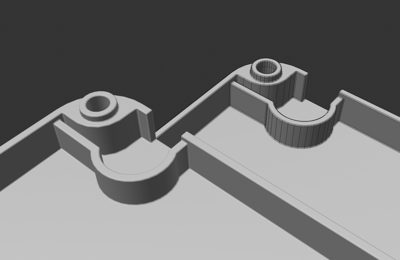
Hi Cerebra, I used a topology method to design the front of the cassette. Do you have any friendly suggestions for things I could tweak or enhance? Attaching the working file just in case.
Subdivision 0

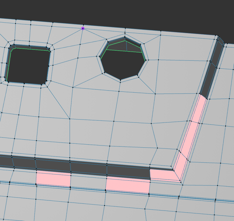
Is it okay to have over four polygons around that hole on the lower-right corner?
Moreover, there are non-planar polygons and a complex pole in this particular area.
 0
0 -
15 hours ago, Stefano Strika said:
I think that for this kind of model you can also use some basic technique like simple booleans, if you take care of the topology and add n-gons where needed you can also use bevel like on a CAD software, here is a very quick example.
Of course you can go for quad modeling but IMO for this specific object made out of plane surfaces and simple curves it may not be the fastest way.
I agree with you. Thank you.
0 -
1 hour ago, Cerbera said:
First of all - are you modelling the outside only or doing the inside as well ? If it's the latter then you should start with the inside, which better governs the polys you actually need.
What you have done here is fine but probably way too high poly - for example that hole on the corner should be able to be described with an 8 or 12 sided disc.
By starting so high poly you condemn yourself to wrangling that increased amount of them all the way across the model, rather than only having poly density you require.
CBR
I agree with you! I am modeling the inside as well.
0 -
5 hours ago, Cerbera said:
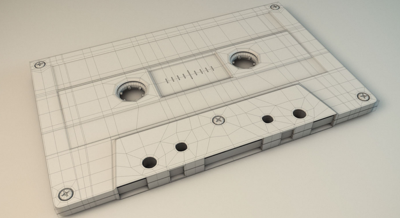
If we're going to do it nicely / properly, a cassette tape is actually quite hard to model in any software, but none of it is unsurmountable if you have good reference and plan your parts, corner types (box vs inset type) and topology carefully.
If you can get away with not modelling the inside (ie your cassette isn't clear material) then the outside is a lot easier than the inside, as your second reference shows...
You would begin this model by outlining the holes and tape guide section, and connecting those meshes together across what is (helpfully) a mostly flat surface, which means you can do any loop expansion / collapsing on flat bits, without worrying about SDS lumpiness on curvature. In that respect it is not strictly necessary to exclude tris or ngons in these areas, but in practicality it makes little sense, and saves little time to do so.
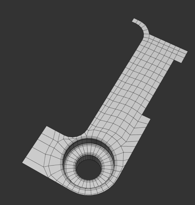
The front half of the case is notably simpler than the rear half, which contains all the extruded parts. It's not as much work as you'd think though, because we can deploy X-symmetry throughout, and all the parts that are chiral are best achieved with separate meshes...
But really your first reference photo is showing you all the prime topology points you have to hit to make that inside, which mainly consists of ensuring you have enough topology to describe the hard edged inner details at the bottom, which then collapses down to less dense poly flow as they get further up where detail is less. Hence the liberal use of kite quads for loop concatenation as we see particularly in the section below...
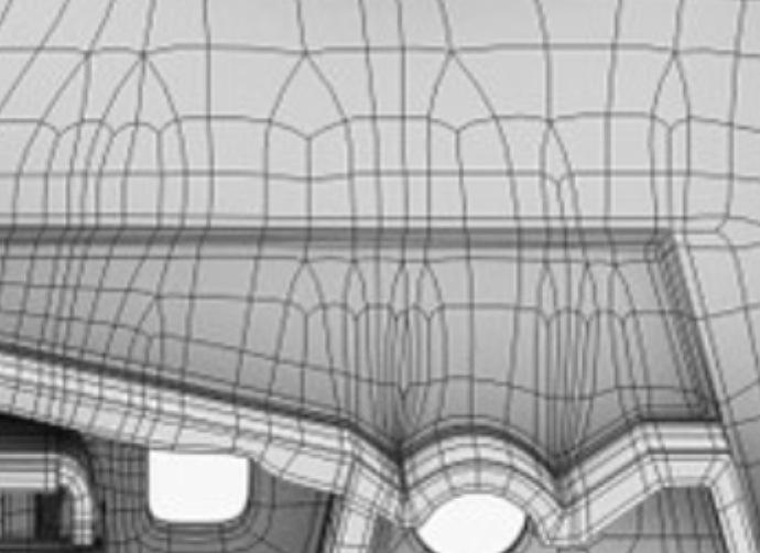
Note the box cornering that goes on everywhere there is a hard defined corner, which is required to stop this collapsing under SDS.
Of course there are a number of lazier, cheat-ier ways to make the modelling easier (booles, volume builder, non SDS etc) but none of those will give you quite as nice results as if you model it poly by poly, SDS, where you have infinite resolution suitable for extreme close-ups. But if this cassette is just lying on a table somewhere at the back of a scene, then a full SDS model is probably overkill.
CBR
Thank you!
I have a question. I'm using the re-topology method at Cinema 4D to reconstruct the existing modeling. Is this method also okay and the right way? It's easier for me.
 0
0 -
Is it hard to model a cassette tape in cinema 4d? and what is the best way to make it clean?
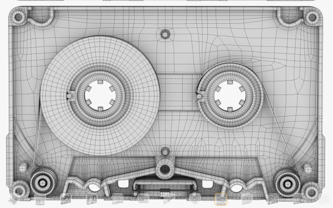
 0
0 -
-
-
8 hours ago, Cerbera said:
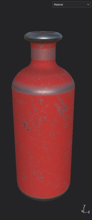
Here is a comparison of 3 of the available mapping methods.
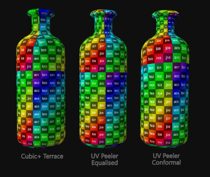
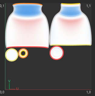
As we can see the cubic terraced islands approach produces by far the least distortion. The not inconsiderable distortion we inevitably get from any version of the UV peeler method is quite extreme if you do the outer and inner as just the single island, even in the conformal relaxed version (image C above) so by doing a cubic approach we spread that distortion out across the 4 areas we allow to remain separate, which lessens it accordingly. The price we pay for this is 4 partial seams per island*
* You may notice that in A, the Cubic version I added a lot more seams than that along the base end to achieve zero distortion in that area, knowing that we probably won't see any seam lines down there...
Note in the main top pic how the squares stay the same size at the bottom of the bottle all the way to the top, whereas the UV peeled ones can help but shrink those polys the higher up the bottle we go, which is why solution A is better, albeit non-intuitively so.
Make sense ?
CBR
So cubic+Terrace is the best solution among those?
0 -
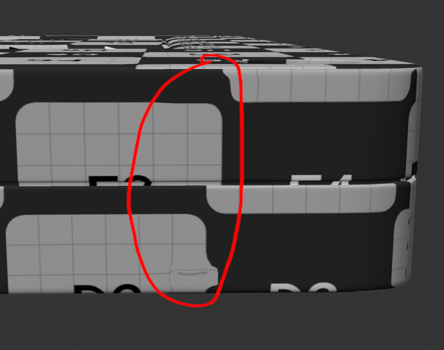
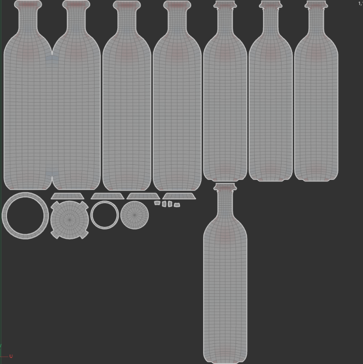
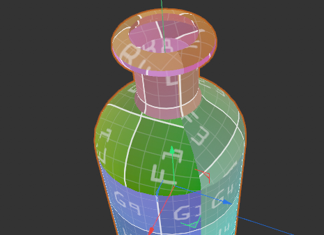
8 hours ago, Cerbera said:
On the contrary, that is actually rather minimal distortion, and should be functionally fine in the render... However you need to continue to terrace the outside islands together and then the inside islands together so that you eradicate 3 out of the current 4 seams on those sections, as you have started to do on the outside. Same on the inside.
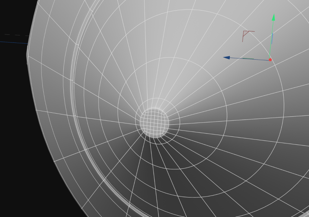
Modelling-wise it's mostly fine, if a little high-poly, except you could quadrify the pole sections so they become non-complex, though it is not really necessary.
CBR
Are these the poles sections you mentioned above?

 0
0 -
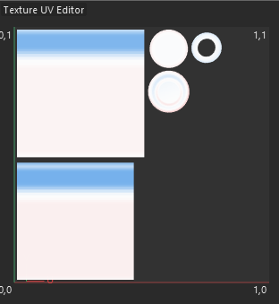
10 hours ago, Cerbera said:
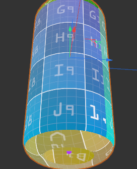
There should be no need for weld and relax because you can use the UV Peeler to get that result directly if you use the correct combo of up-down / left-right as you drag. And indeed this method is perfect for straight cylinders where there will be no distortion. However, as soon as your bottle contains curves - ie the radius changes up the length of the bottle, and for example, you need something like embossed text running up a curvy section of the neck, the UV Peeler can't help you, which is why I suggested the cubic method, which at least shares that distortion over 4 quarters, which is often preferable to either proportional or equalised result you can get with the peeler. Just a thought... make sure you have Distortion (from UV settings menu) turned on and up to 100% so that you can see how much distortion are getting with the various methods..
CBR
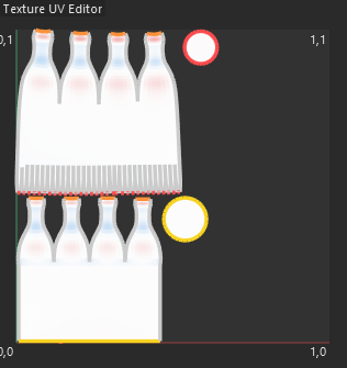
However, there are many distorted parts over there. Is it okay? Could you help me with UV unwrapping, including modeling?
 0
0 -
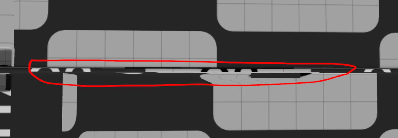
I'm planning to bring this bottle to Substance Painter. Is this well unfolded UV map? The central part seems to be well unfolded. However, the UVs on the upper and lower parts have different angles, and I'm not sure if that's okay. Near the seamline in Substance Painter, the mapping appears oddly.

 0
0 -
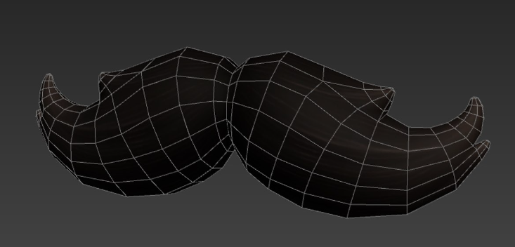
Can you help me with this 3d mustache with low-poly? I'm trying to create the white mustache in C4D. Also, attaching the reference that I found.

 0
0 -
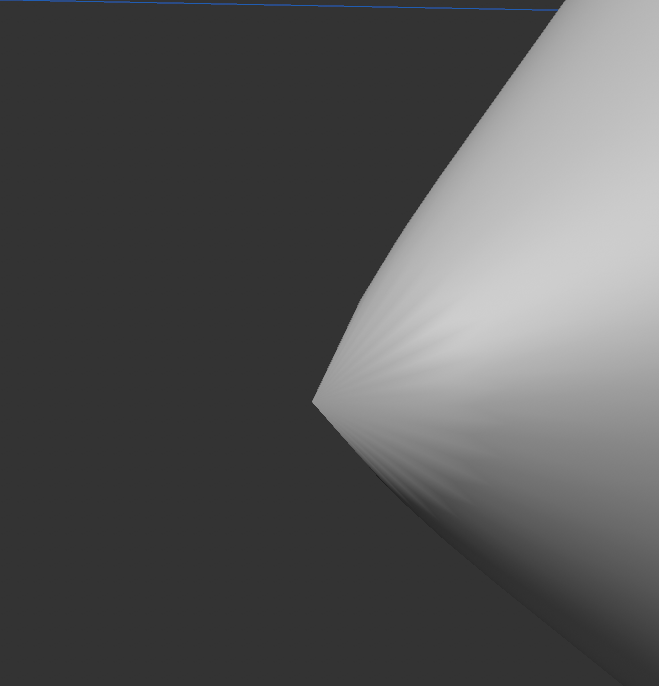
12 minutes ago, Cerbera said:
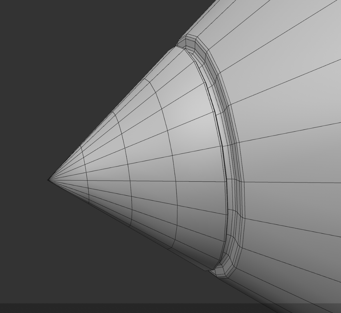
OK, well the end of a pencil is not actually a point, which very much helps us here, because we can just bevel the point you have to turn it into a flat disc you can angle rakishly, or leave straight as I have done here, and patch to quads...
Then we just need perimeter control loops to isolate that from the nib loops to avoid the distortion there.
CBR
Thanks!
0 -
Just now, Cerbera said:
Still doesn't show wider context. I need the file.
CBR
Oh! Here we go.
0 -
2 minutes ago, Cerbera said:
Need to see the wider context of the mesh. From the screenshots that is too many edges conflate on a corner.
CBR
It looks like this before adding subdivision surface.
 0
0 -
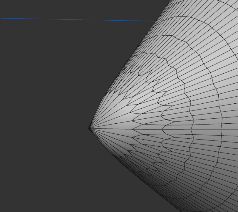
My question is how to make the round round? Please teach me kindly. Thanks!
 0
0 -
Does anyone know how to adjust the black shadow around a object to make it realistic?
 0
0 -
4 minutes ago, bezo said:

You're my life saver! Thank you as always.
1


Pickleball Modelling
in Cinema 4D
Posted
Hello, I would like to model a pickleball with 40 holes. Can you teach me how to model it?