

Jaee
-
Posts
320 -
Joined
-
Last visited
Content Type
Profiles
Blogs
Forums
Gallery
Pipeline Tools
3D Wiki
Plugin List
Store
Downloads
Posts posted by Jaee
-
-
9 hours ago, Cerbera said:
if you remove that plugin does the problem persist ?
CBR
Yes, it does...The hotkey 1 2 3 doesn't work in the C4D viewport. I've removed the Quadcaps folder from the plugins folder, but nothing changed...
0 -
Hi guys, I've purchased the Quadcaps plugin and installed it to my C4D R25 successfully. After then, my keyboard stopped working in C4D. Does anyone know how to fix the issue and what is the problem? I've restarted my computer several times...but it didn't work. The plugin seemed to work.
0 -
On 3/25/2022 at 2:33 PM, Cerbera said:
No, that's exactly the same as the top was... just apply those techniques to the bottom as well.
If you really do need step by step the whole way through, then perhaps book an hour of my time to go through it with you over skype or similar - that is a service I offer...
CBR
Thanks Cerbera!
0 -
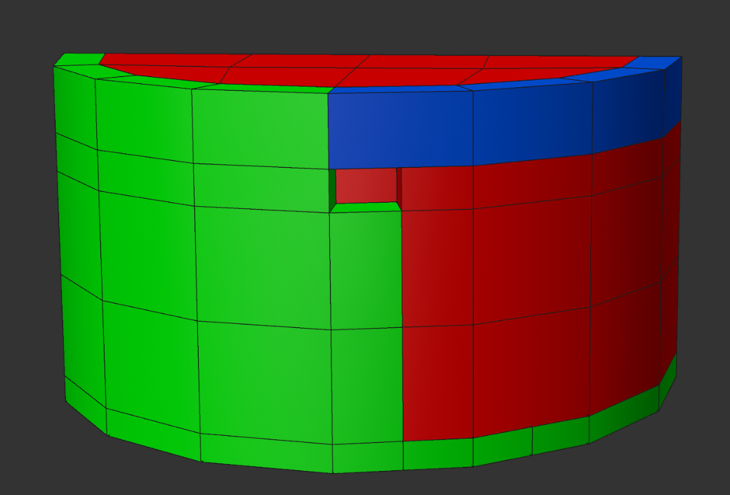
19 minutes ago, Cerbera said:
Sure. It is not possible to extrude this one manoeuvre, so we have to do it in several manual stages.
Start with this (and possibly another disc section on the lower base, which I didn't bother with for speed's sake)...

Then select these polys, and extrude them out (with caps, 0 segments).

Now select the rim edges thusly, ctrl-scale those out from centre of circle until they match the edge extrude. Weld the points by green arrows.

Next we should extrude the entire top cap (with caps again), but then we should remember to go back and delete all the non manifold edges we have just created by doing that, so select them first for easy deletion when they are covered !

So, extrude the top now, then optimise the mesh, then go inside the top section and delete all the non-manifold polys (those that connect to more than 1 surface).
That should give you this result, which just needs you to pop these support loops in at the top...

...you can scale this polys out from centre to get the outer base ridge...

I didn't do in integrated base in mine, but the same principals apply... and if you get your control loops right you should get this nice tight result under subdivision... so we have to add several supports around the base, AND some in the rim thickness itself, which we didn't add during the extrude as it overly complicated things.

CBR
Could you teach me how to add the bottom part like the entire roof?
0 -
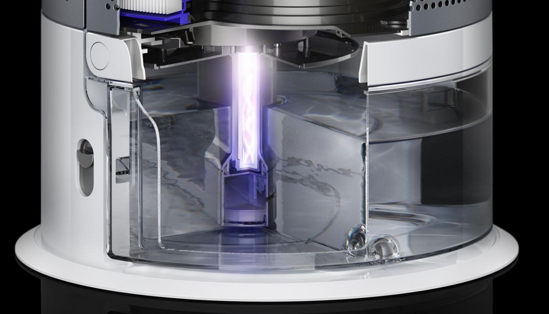
On 3/23/2022 at 11:24 PM, Cerbera said:
Actually no, I think the water jug bit goes into the rear half as well, so the outer has to be hollow.
In which case I would add the roof and floor (but no control loops by it yet), then add negative thickness and then add the control loops, giving you something like this...

CBR
it looks great! Could I know how to add the entire roof, not the half of roof?
0 -
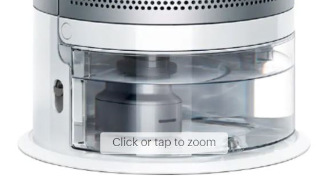
13 minutes ago, Cerbera said:
Trouble is, that is not enough reference to see clearly what that part does behind the clear plastic bit. But I think it should start from this sort of thing, and not with adding thickness as you have tried above...

CBR
hmm...
0 -
11 minutes ago, Cerbera said:
Yep, that should be fine.
CBR
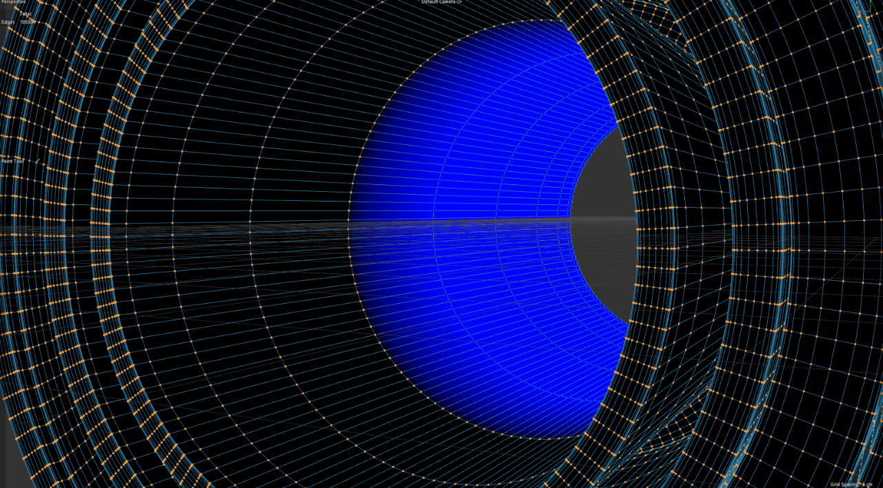
When I extrude the mesh...it looks very weird...like this.

 0
0 -
2 hours ago, Cerbera said:
Sort of. The hole in your reference is much lower than where yours is now, and you'll notice mine is separated from the nearby edge but at least 2 loops, which keeps that area nice and controlled where it meets the edge. Lastly, you don't have a box corner here, so your corner will collapse too much under SDS whereas my (latter) example would not...

Also note how my large corner is not 90 degrees like yours, but actually curves in to describe it...

CBR
Does this work?
 0
0 -
53 minutes ago, Cerbera said:
Yes that'll work, but don't add the thickness to the wall section so early. Get all the topology in you need, including the edge flowing loop in my example above and the cut-out button bit BEFORE you add thickness, otherwise you'll be doing all that twice and trying to make it match on both sides !
Lastly, note additional horizontal loops added to the middle of the button to more tightly define the rounding there...

Lastly, I changed my mind about that top right corner part, and made it a box corner instead of an inset type, which results in much less of a curve there now.
CBR
Is this correct?

 0
0 -
1 hour ago, Cerbera said:
As usual, I have to say, not enough radial segments in that plan. Curvature has to be established to a much higher degree when we want curves like that.
This started off as a 48 sided cylinder...

CBR
Do you think this mesh would work? Am I doing in the right way?

 0
0 -
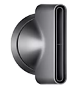
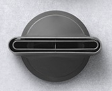
I am struggling to model the bottom part of this Dyson Humidifier in C4D. I have built up some basic shapes of it. But, it was hart for me to model that rounded edge shape. Could you give me a hand? I've attached my C4D working file below.
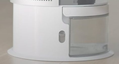
More reference below_
 0
0 -
Hi, I am trying to model this part of a hair dryer. Could you give me a tip to start modeling from scratch? Thanks,

 0
0 -
Is there a way to sharpen that blue color vertex map border line in C4D?
 0
0 -
Hi guys, are there any 3D Design or Motion Graphic Design competitions that can be entered individually or as a team?
Thanks,
Jae
0 -
On 4/9/2019 at 2:31 PM, Cerbera said:
Does anyone know how to post in the right place !?
CBR
Where the question should be placed?
0 -
I don't want to see the pop up window when I open Cinema 4D R20. Does anyone know how to delete the substance asset permanently?

 0
0
Quadcaps / Keyboard not working in C4D
in Cinema 4D
Posted
I just tweaked something in command manager. The problem is just fixed...It's very very weird,,,