
Cerbera
-
Posts
17,954 -
Joined
-
Days Won
733
Content Type
Profiles
Blogs
Forums
Gallery
Pipeline Tools
3D Wiki
Plugin List
Store
Downloads
Posts posted by Cerbera
-
-
New plastic did a whole series on Afro hairstyles, and it was absolutely brilliant ! He was using octane at the time, but a lot of it still applies.
Here's the first one...
CBR
0 -
Hey Doug. It's a perfectly valid question, and one we have all wondered about at some time or other...

Open Charmap, directly from the Windows command prompt, and select the font you would like, and find the character(s) you need, then Select (that's how you can get multiple characters at same time) and Copy them (Ctrl-C), and paste (Ctrl-V) into Cinema's text field.
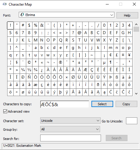
Would be nice if Cinema could do that bit for us though, so might suggest it, although I can imagine the reasons they might give why that's not possible.

CBR
0 -
14 hours ago, HappyPolygon said:
It bridged fine when I enabled the Reverse option and set Spin Steps to -1.
Indeed it did, and if we change the mode to Surface as well we even get the curvature we need automatically !
Looks like those specific settings evaded me when I first tried !
CBR
1 -
1 hour ago, Freemorpheme said:
Thanks for that. Did you bridge it with theStitch and Sew, then add the other subdivisions in with the knife tool? The S&S tool just makes one giant bridge for me, or 2 if I press CTRL.
Yes I popped the new segments in with Edge Cut.
CBR
0 -
Yep, Bridge can do that...

Settings thusly
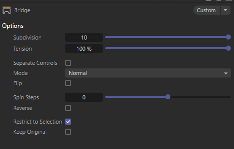
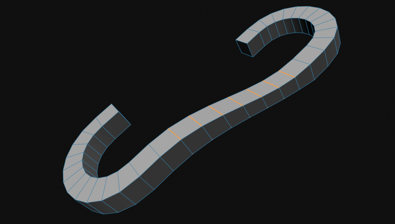
However in the precise example you gave, then yes it can do it, but you can see below, it currently breaks if we try and connect offset pieces.

There we are actually crossing polys half way down it, which is obviously useless, which I will report as a bug, because I think it should be able to do that ! You can see it's got the right idea, but has failed to execute.
And so we must instead delete the end faces and do it with Stitch n sew instead. I used the shift modifier for that, which, interestingly, failed in exactly the same way the bridge tool did, so I had to use Ctrl modifier instead - not ideal, but it worked ! This can't put the sexy curvature in tho, and although it is relatively trivial to pop that in manually, but with Bridge tool working as intended we shouldn't have to !
However, to pop that curvature in in a semi-automatic way, we can can always just select the top and bottom edges in that section and Set Flow them, which does OK...
So yes, Cinema can do it, but few more steps than a single tool.
CBR
1 -
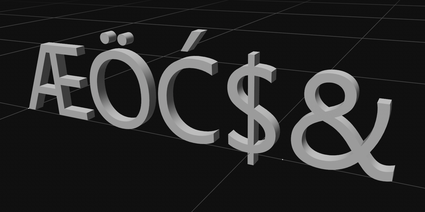
Ok, so 2 things contributing to that.
1. Your phong tag has Use Edge Breaks active.
2. In the text object your caps / bevels have the phong break rounding box enabled, which it is by default.
Disabling either of those should remove the dividing line between beveled cap and rest of mesh. However, does tend to lead to messy results on the corners of the bevels, as we see below, so mostly it is preferable to leave that on.

A messy, non phong-breaked corner, earlier.
You'll notice on that particular text object that adjacent topology changes as it goes round the corner, and this is only cleaned up (ie cut / truncated) by the solve intersections checkbox, which we also need here for beveled caps to work in most circumstances. I would agree it is perhaps not the most elegant of solutions, but it is what it is in order to give easy access functionality all within 1 single object, which is rather what the Text Object is all about ! We should be able to circumvent some of these problems by using a bevel deformer instead, where we get more control, but again I fear that geo mismatch at the corners may lead to rounding artefacts anyway, despite the better control / ability to only apply it to certain edges / and manual phong break advantages.
OR at any point you can make the mesh editable, and then manually select the edges you don't want phong broken and then use / unbreak phong shading command (I get it from down the very bottom of the right click menu) to remove that hard edge specifically without affecting the corner ones...
It probably is worth noting that if we use the 3rd option in the text object rounding department - bevel outside - that actually solves the corner phong beak scrappiness because no geo is intersecting badly like it was before, at the expense of slighty 'fatter' text !

And then, if you set your phong tag angle to something low like 18 degrees, you can get the best of both words, thusly...

But then of course we have this massive discrepancy between rounded bevel phong shading and the razor sharp edge running back away from the caps, and a fairly grim transition between the 2 on that corner...
So lastly, the phong tag itself can help us there. By setting the angle in there waaay high instead, and changing the phong type to something like Angle and Area weighted we can improve it again, and gain consistency of shading in the bevel AND back across the mesh, so I guess this is the ideal solution in your case.

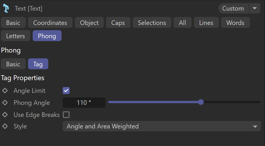
We can see this better if we zoom out a bit and look at the 'B'... very nice consistent shading everywhere.

CBR
2 -
Always share the scene ! For example we can't see what your phong break settings are, either in the bevel properties or in your phong tag. And that's where I'd be lookin' first...
CBR
0 -
Slightly mystified how we can help if we don't even have your scene file, but nonetheless I shall try....
Have you done everything in this video, specially relating to cache output settings ?
CBR
0 -
Yes I used to get 2 or 3 modelling Qs a day, vs the 2 or 3 a month I get these days. Cinema's help is pretty decent these days, but there should still be lots more to answer.... Places like this are important, and communities should support them and use them more ! I much prefer dispensing advice and learning new things here over places like Discord...
CBR
0 -
9 minutes ago, HappyPolygon said:

This doesn't sound logical to me...
I mean, if you are a software corporation you have people with all kind of software skills, one has a Master's in Real-time Render, the other in Physics Simulations, the other in Animation... isn't it only logical to group them in teams each assigned with a task closer to their expertise ?
Shouldn't every C4D update be "global" ? Should I believe that every dev is working on liquid sims and not on an improvement on BodyPaint or Fields ? Do they just hire and fire people depending their "focus" if that focus isn't part of their skills ?
Particles look very capable to me. I have very few recommendations left for that system. Liquid RnD shouldn't take too long once the particle behavior foundations are set... For all I know Liquid sims are a Mesher system...
I didn't mean to imply that particles et al were the only things being worked on - I don't believe that's the case at all. There are constant fixes for all sorts of bugs all the time of course. But where whole tools would benefit from rewrites and more fundamental updates I just find that Maxon tends to address a lot of those sorts of things all in one go every few years where a suite of tools in a similar area becomes a highly focused effort for a time, such as in the 'great modelling overhaul' of R18 for example, or the large push that happened a few years later that saw all those extra QoL tools added to modelling toolset (Fit Circle, Equal Spacing, Smooth Edge, Relax Brush etc etc)...
I merely express the hope and my confidence that those won't be the last !
CBR
1 -
As a typically staunch promoter / defender of Cinema's modelling toolset I still can't argue with your criticisms of those 2 aspects of it. There is certainly much to be done by way of improving both Line Cut and Poly Pen, particularly relating to their behaviour around ngons. But me and a fair few other modelling-focused testers have good coms with Maxon and ensure they are fully aware of our frustrations, and we do constantly push for improvements and fixes to the modelling tool set. And Maxon do listen to those concerns, fix what they can as they go along, and bank up ideas and retooling plans for the next time modelling is in 'dev-focus' so to speak...
At the moment, unsurprisingly, it's Particles and Liquids that are getting a lot of focus, but it'll be modelling's turn again soon enough I imagine...
CBR
2 -
The OSL ones have been available on GitHub for quite some time, but when I last checked them out it wasn't a Maxon-specific page of them. I didn't know about the Python one. Definitely some very useful shaders and extensions there.
CBR
0 -
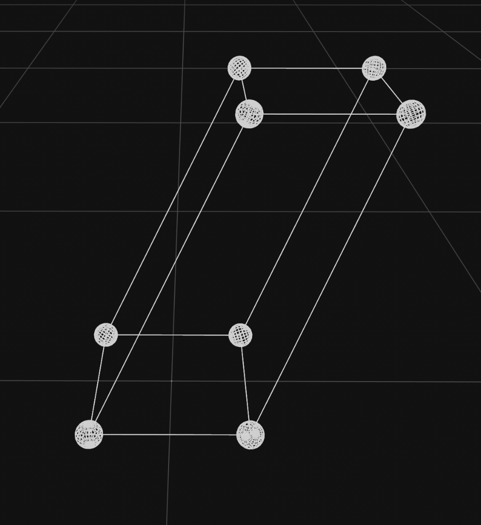
Well that's why the phong doesn't work ! Mesh checker reveals that no polys are actually connected to each other !
CBR
0 -
1
-
Oh DF, you are so very good at finding the Achilles heels in fundamental tools
Alas, merely flattening that row of polys will not give you the droids you are looking for...
The reason is that with that topology, as theoretically ideal as it may seem, we are asking way too much of SDS here - it needs considerably more help than that to solve the shading issue.
Let's simplify in order to better explain.
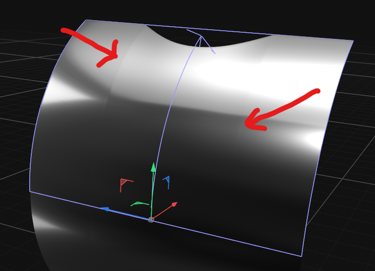
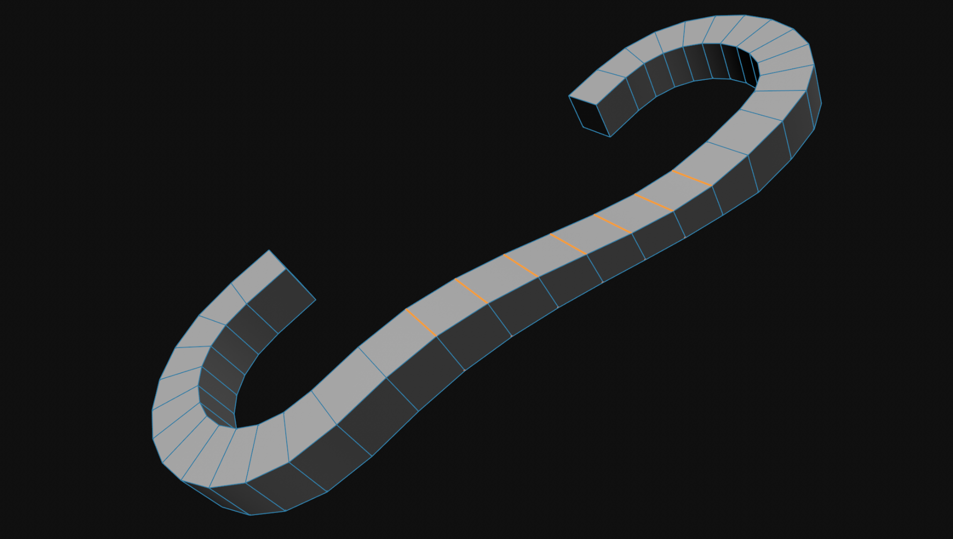
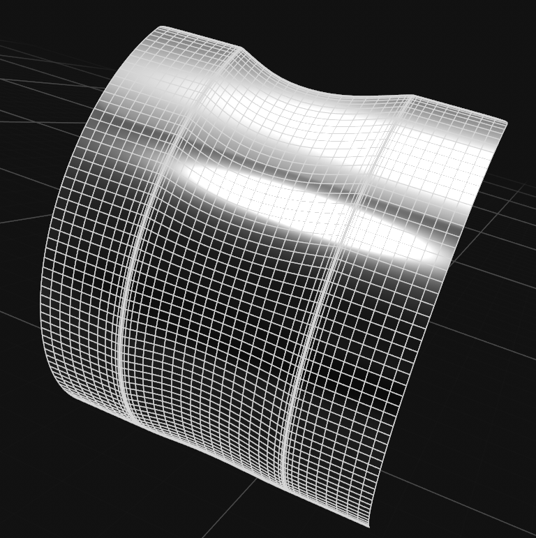
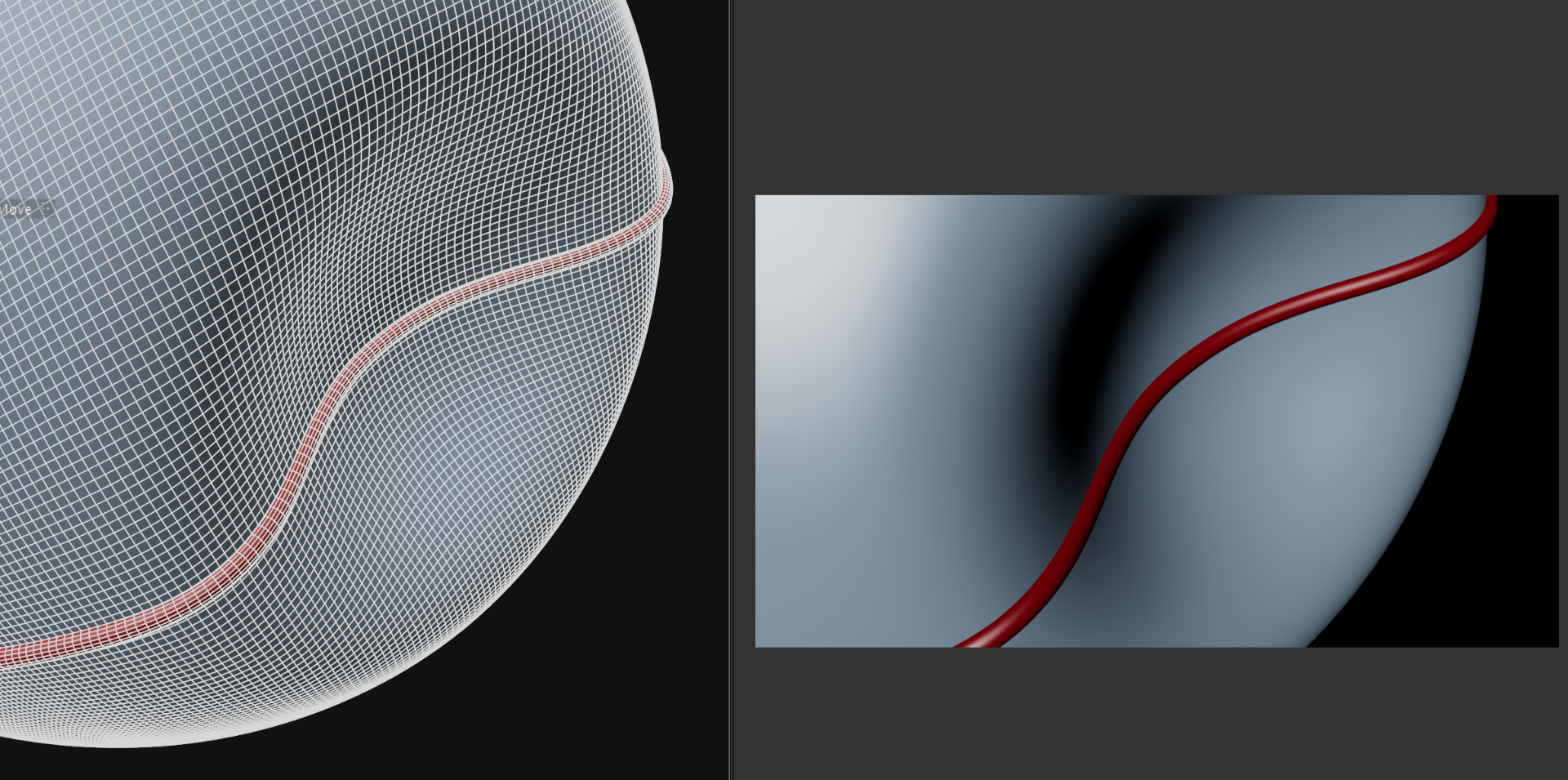
Here is the side of one section of your tubing before it is curved, but even more perfectly even than your original, and for now without any control edges...
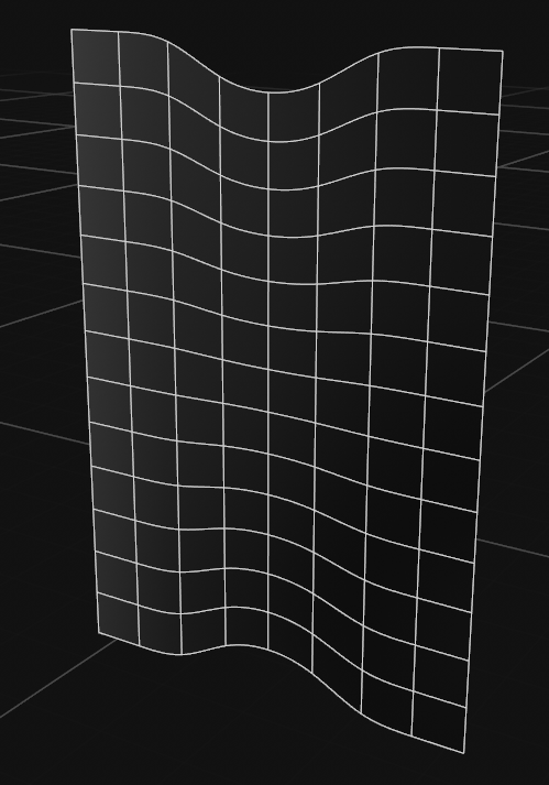
Now, if we add an experimental bend to that, (occupying the top half of it, and in unlimited mode so it does both ends at once) then already the SDS shading is disturbed, but because of the polygon evenness and lack of control edges we can't really notice it.
However it is there, as we can see by the breakup that arc into a dot and a line...
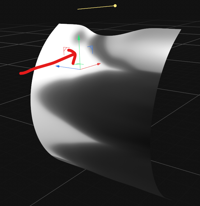
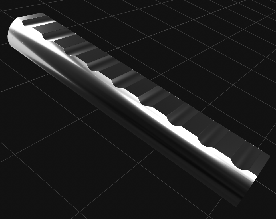
Let's add some control edges to our base mesh that so our groove isn't floppy, which will make the problem much much worse !
So now if we try and bend this...
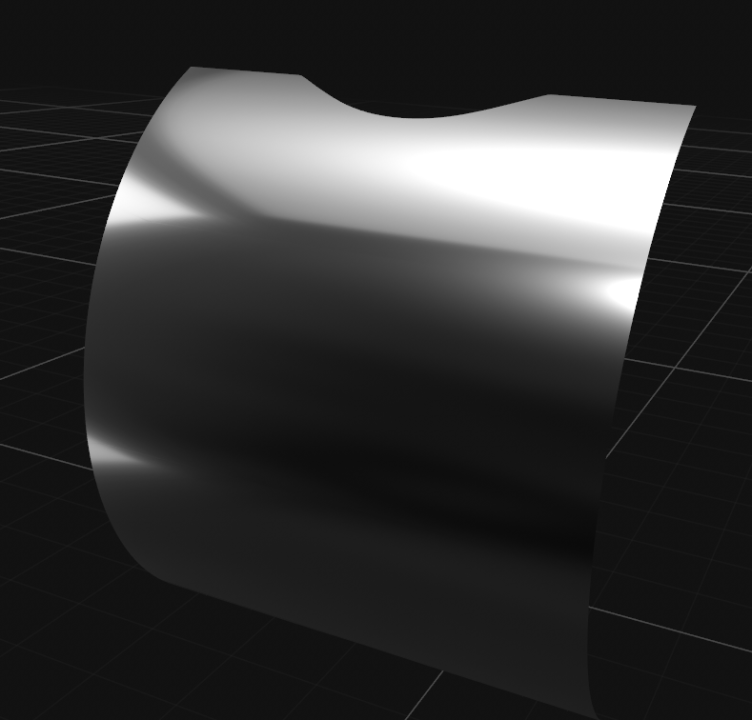
Then we will get this... in which the horrible shading is fully restored and visible...
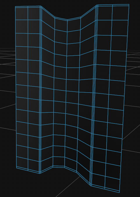
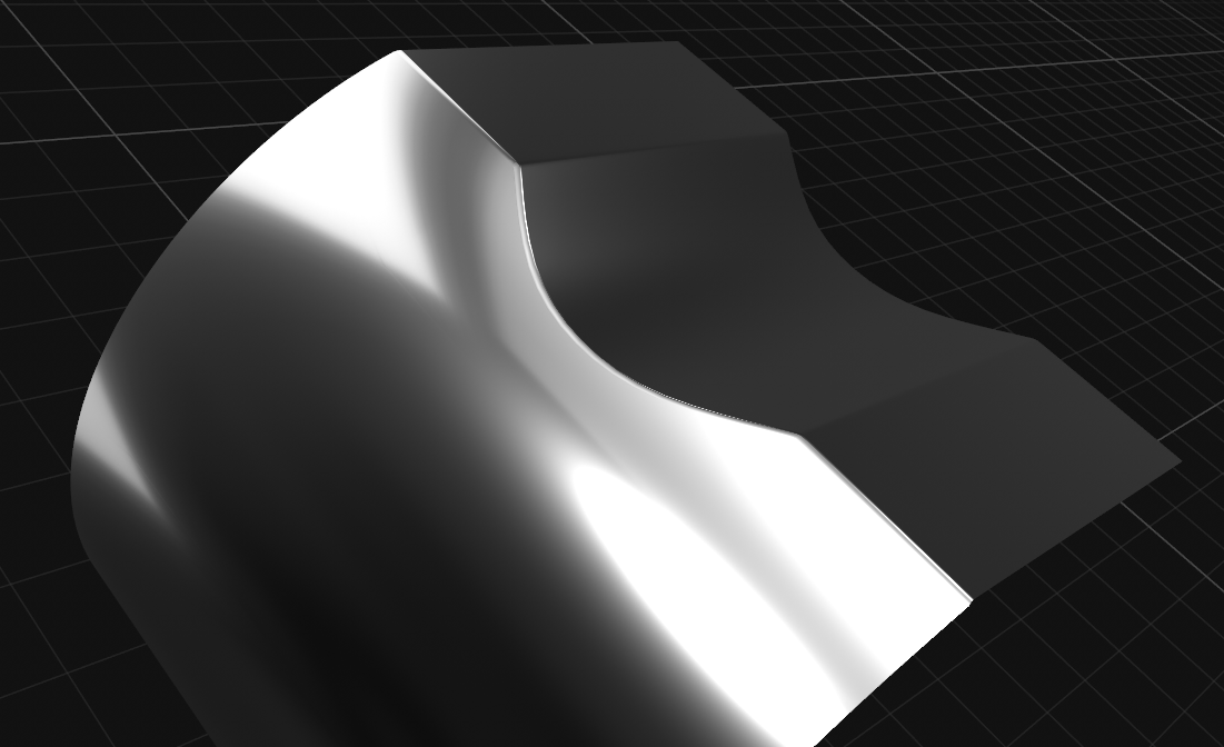
So, what can we do about this ? Well, we can move the bend deformer for a start ! Let's bend the SDS result rather than the base mesh...
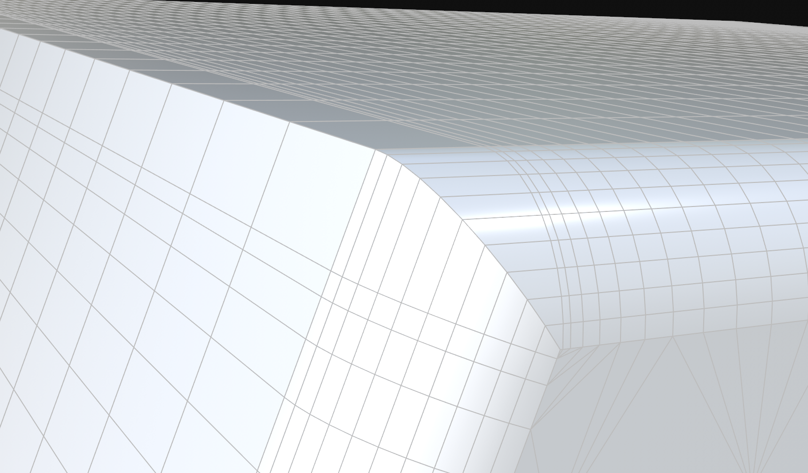
...and there we go, shading problems disappearo ! Now let's have a look at the sort of topology density we have had to bend to get that...

So the answer here, which I know you will hate is to generate these curved surfaces first, CStO the SDS result, and Extrude your flat bits across the top / bottom from there, at that polygon density...
So what is happening there is that the shading problem (which is still there) is rendered virtually invisible by being averaged across so many tiny polys.
And so if we do put this under Level 1 SDS (that's all it might need now given the already applied subdivision), our shading problem remains (visibly) absent.
So, TLDR version would be: Weakness of SDS - needs a shitload more polygon density to circumvent !
Hope that helps...
CBR
1 -
Very difficult to say without trying stuff first. It helps tremendously to have your scene file in trying to help with things like this... Can you upload it ?
CBR
0 -
Yep, came here to say exactly what HP did. Single frame swap-out with unsplit version is traditionally how this is handled.
CBR
0 -
Hmmm. My understanding of this whole space time thing is quite limited ! Are you sure humans are meant to be thinking about this sort of thing ?!
More seriously though, I have trouble trying to translate these sort of questions to the sort of perspective / ortho / parallel views we have in Cinema.
So, still exploring the theme that simplest may be best, what about 3 shear deformers on a cube, aligned to X, Y, Z accordingly ?!
CBR
0 -
Does a shear deformer on a cube not give you what you are looking for ? Keyframing the Strength attribute for animation...

If not there's always pose morph, which is where I'd be heading next...
CBR
0 -
20 hours ago, HappyPolygon said:
Where did all the comments with the waves go ?
Yeah right ! Including my one where I said pretty much what you did !
Perhaps there has had to be some restoring from backups or something ?
CBR
0 -
Very pleased to hear that Rocket Lasso is back in action after a very long time away, starting with Season 7 Ep 1 tonight at 8 pm (BST).

CBR
1 -
I haven't done this myself so far, but I suspect the best way to go here might involve cycloid splines, blend mode cloners and Field Forces.
Searching around those terms I found this tutorial from Insydium.
Obviously, they are using their own particle system, but there is no reason to think the native one couldn't also do it... though I am probably not the best person to advise on the specifics of that; I don't have much experience in Cinema particles yet !
CBR
1 -
I haven't watched the series yet myself, but that title sequence is wonderful.
And the music is as harmonically interesting as the visuals and techniques are to us CG guys. Perfect alternating consonance and dissonance.
For those of you who have an interest in such things, here's Charles Cornell to explain why that's also great !
CBR
1 -
There are, if we look carefully, a number of things subtly wrong with the settings in this scene.
As HP predicts above, Render Perfect on the sphere is one of them, and fixes the effect of collision deformer not showing in render if we turn that off.
Next we had some suspect settings in the sweep object (parallel movement should be off, Banking should be ON, and End Rotation should be 0 degrees), which fixes the twist in your path spline over the indent, and restores it to correct, contiguous circular form all the way along its length...
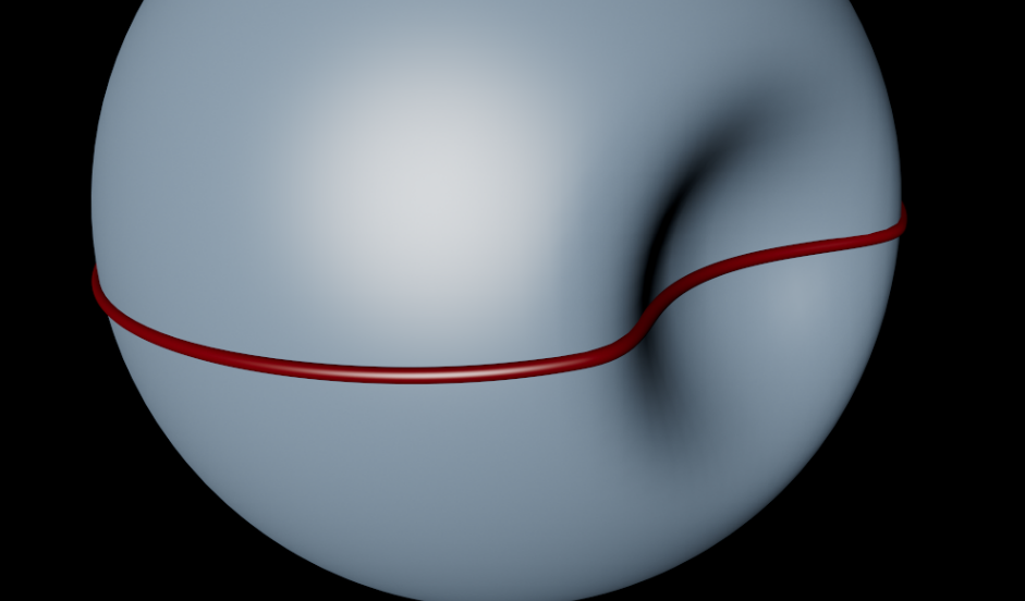
The mode of the Collision Deformer should be Outside (volume) and the capsule should ideally not be a child of it, though it doesn't particularly matter in this scene.
Likewise object order in the OM could be better bearing in mind that Cinema scans downwards through it from the top.
Below is more ideal I would say, and general good practice.
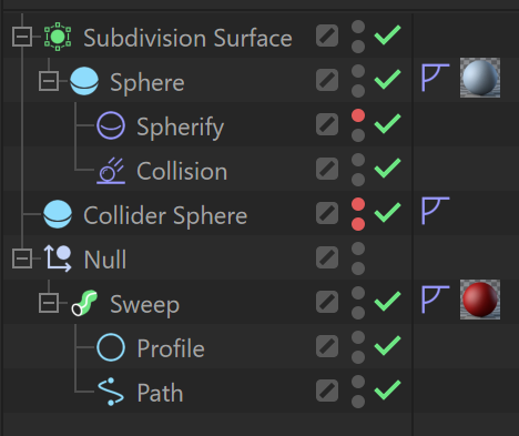
Next, the curvature in your path spline within the sweep isn't quite matching the curve of the indent in the sphere, resulting in some unevenness in that area. This can be fixed by getting a new path spline for the sweep, which we get by doing Current State to Object on the main sphere (once collided) and then Edge to spline on the centre edge loop of that, but first we have to fix the collision object, which should also ideally be a sphere so that we can choose Hexa type and thereby avoid the complex pole on the end of the capsule it replaces, which was previously confusing the collision deformer, and producing some wanky / uneven collision vertices in the main sphere at the apex of the collision point, which would obviously effect any spline you subsequently derived from it. In my version I wanted a better, higher resolution sphere, but not one that caused the collision deformer any extra work, so changed the type of that sphere to Hexa as well, which then necessitated addition of a Spherify deformer before the Collision Deformer (because hexaspheres are not mathematically spherical out of the gate).
And then lastly that went under SDS to give us improved resolution, and my Current State to Object was performed on the SDS instead of the sphere itself, for maximum spline matching.
Anyway, I have fixed all that in the scene attached below...

CBR
2


Redshift camera showing reverse perspective from my scene
in Cinema 4D
Posted
Your listed version number is 2025.1.3. We are up on 2025.2.1 now, so that's the first thing to check.
Then we could look at what video driver you have installed.
And we could do with a couple of comparative screenshots as well, to check that what you are actually seeing matches the words you are using ! That wasn't meant to be as condescending as it sounds - it's just that a term like reverse perspective could mean a few possible things in 3D space, and we need to know exactly what you see so we have a fixed point to start investigations from !
Having said all that, I am not the person to assist with this, being one of those people who seems to be leaving the Win 11 upgrade to the last possible moment - I haven't done it yet.
CBR