

Cerbera
-
Posts
17,815 -
Joined
-
Days Won
698
Content Type
Profiles
Blogs
Forums
Gallery
Pipeline Tools
3D Wiki
Plugin List
Store
Downloads
Videos
Posts posted by Cerbera
-
-
Not so silly a question, but it does have simple answer. Alas that answer is no, unless the other tags are attached to children of the first, in which case you can use 'select child tags of similar type' from the r-click or Tags menu.
CBR
0 -
There are some free tutorials that show the entire process, but as has been mentioned, not in C4D. However the techniques are largely the same so if you have basic knowledge of the C4D modelling toolset you should be able to see the equivalent Cinema processes. This one for Blender is fairly comprehensive and that guy properly understands the thinking behind modelling this sort of thing.
Likewise, check out Arrimus3D, and search his channel for car questions - he has many videos about how to solve difficult automotive curvature problems (he's in Max) but he is genuine topo master so well worth absorbing his tips.
Patch Modelling is what most people use to do this, but Cinema is rather limited in that respect, although you can re-purpose tools like Loft or Bezier Surface to achieve similar things. Or you can download the free Coons Mesh plugin from MAXON Labs, which can create patches based on intersecting splines. Or buy Spline patch, which is like that but a lot better.
CBR
0 -
19 hours ago, VanderAGSN said:
including the camera which returns in viewport
Forgot to address this one. You can turn that off in the View Settings / HUD menu. If you then save your layout as default you'll never see it again !
CBR
0 -
In Cinema that's called (rather more appropriately IMO!) Collapse (U-C), although Weld (M-Q) does mostly the same thing in this instance. So you'd just Inner Extrude (I) that big n-gon one more time to add another edge loop, then use Weld or Collapse commands (r-click menu) to reduce it to a single point.
The difference between the 2 tools is that Collapse ONLY collapses to a single central point, whereas Weld offers additional control in that you can choose the point it welds to.
CBR
3 -
10 minutes ago, VanderAGSN said:
Can you tell me where it is in more detail? I can't find this option now
Its the last option in Window / Customisation menu (Save as Default Scene).
CBR
0 -
33 minutes ago, bezo said:
when opened chess game and try to open Edit/Preferences, opened window has broken layout
Dammit, and I thought I'd be the only one to actually check CHESS with R21 - and didn't find that bug myself !
But actually, believe it or not, this has already been reported !
Cheers dude
CBR
0 -
No, like Bezo I don't think there is. Those exist in all layouts, and can't be removed like conventional icons can. However they are also in Render Menu so there is a valid case to be made for having their appearance in the main GUI as an optional preference. Why not suggest it to MAXON via their web site ?
CBR
0 -
I think I'd describe one of those as 'major', and the ProRender issue is already under investigation, but thank you for reporting it nonetheless.
As far as affected systems go it certainly isn't all of them, as I have functioning ProRender in my R21, and I don't even have hardware that properly supports it ! Anyway, hopefully it will be fixed soon for all systems.
I can confirm that the Bold Interface option (or rather its lack of appearance after restart) is also the case for me, and I have reported that for you.
Alas I am not in a position to test frame rates, so can't comment on that, but please do report that yourself via the MAXON Site or via Support.
As far as the grey / blue goes - have you found the option in Project settings that lets you change Default object colour back to the original it always was (listed as grey blue in the drop-down) ? There is no set as default for that because Project Settings are saved with the default scene, so just do that instead with the handy new option for it under Customisation menu.
AFAIK, I don't think you can remove the Node Space option, but I wouldn't call that either incomprehensible or useless, however it is available elsewhere (render menu) so I can perhaps see why there should be an option to remove it from the GUI. You could use MAXON's Suggestions Page to suggest it to them...
CBR
0 -
It's quite hard to use edge weighting in a way that doesn't cause some render artefacts somewhere. It is almost always preferable (in terms of result, if not time) to do it with control edges and not using SDS weighting at all if you can. Also worth noting that this weighting is not necessarily interpreted the same in all programs, so if this model is going anywhere else at any stage, that's another reason not to use it. If you must use it (for time reasons), then try and limit its area of influence by using some control loops as well.
CBR
0 -
Thanks Bezo - I'll check these for reproducibility / have a look and see if any of these haven't been reported, and will do so for any where that is the case... Personally I think I've had No 3 before, and suspect no 5 is known, but the others are new to me...
CBR
0 -
He is using high sub poly displacement, which you don't seem to have turned up above 2. Make that 6 and you might be closer. It will still take ages to render. Of course it is slow AF with that many polys and that much calculation being done at render time...
CBR
0 -
A quick word about texturing. Make sure you keep different save files for the various stages of this, as it makes sense to do the texturing as we build the main leaf. I'll be back at some point to show you that, but the key is to texture each part BEFORE you collapse it down with others. So in the case of this, you want to texture the first leaf before it goes in the cloner... This could be as simple as a mirrored gradient or you could properly UV map a photo or prepared graphic to it if you really are going for realism...
CBR
2 -
You're welcome. I'm out gigging all night shortly, so will have to show you the rest tomorrow, but here's the first 7 stages of a high-ish poly 'hero' fern...
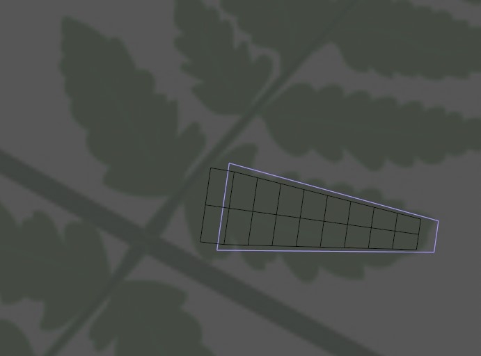
1. Get a suitable reference image of a fern off google and load into top viewport. I went with this one. Line up a plane over the bit shown with its Z axis pointing down that frond.
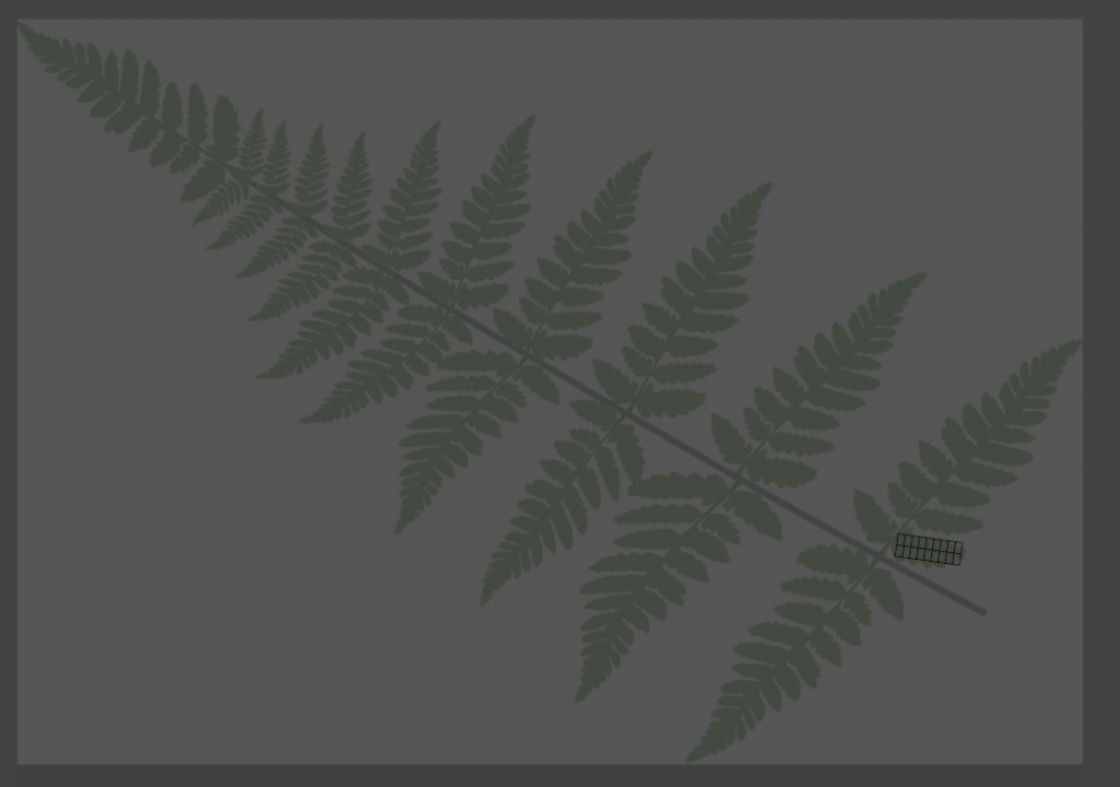
Let's get a zoom in of that...
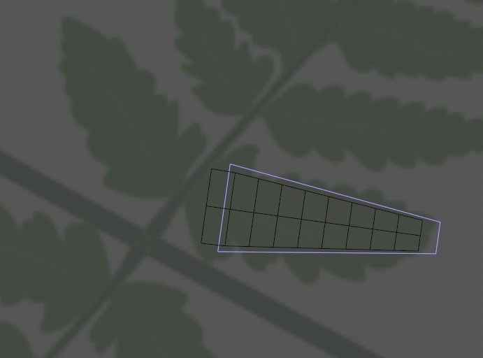
2. Above I have given my plane object 8 or so segments down its length, and 2 across. Then I have applied a taper deformer as a child to generally match the form of that frond.
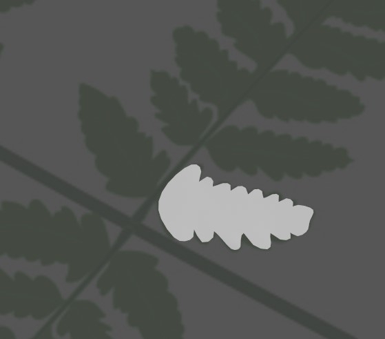
3. At this point you can 'Current state to object that, then delete it to collapse to an editable mesh for further modelling. That further modelling involves edge mode, and selecting edges (or pairs of edges to ctrl+drag out to make the little leaf edge bits like so...
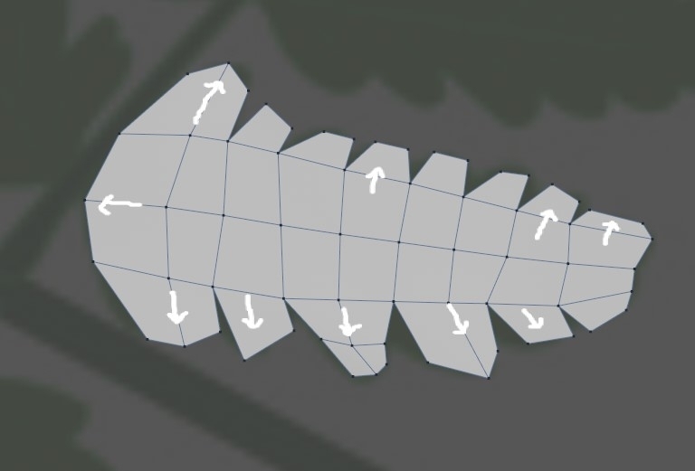
I used poly pen to quickly do this in Top view. You just need a general approximation of the shapes - don't spend too much time fussing over detail, this is a very small part of a much larger thing... anyway, back to the plot, if we put this object under Level 1 or 2 Subdivision Surface Object we get a curvier result like below...
Next we need some copies of that, and so we need a cloner... we will use that just to get some rough copies with some scale variation, then make it editable, and move the individual leaves so that they match the reference.... (Note: clone the model NOT the SDS - Later we will apply the SDS to the whole group so we only need one of them).
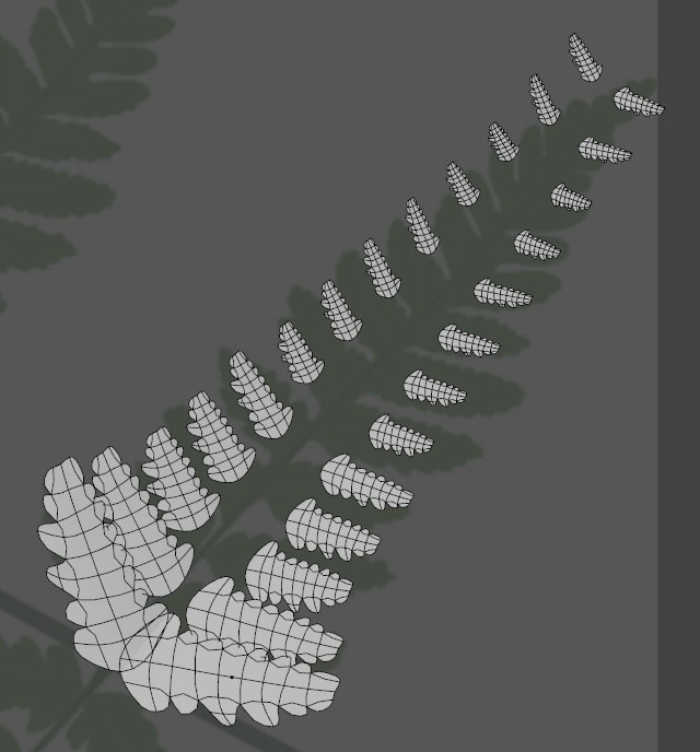
4. Put the frond model under a cloner, and adjust the position values so you have a line of them iterating vaguely as above. I then used a step effector and a random effector to add variation to the scale of the clones. I don't care about actual leaf position because we'll be moving them individually later to match the reference. Note: above I also put my cloner under symmetry, to check how it looked, but we don't actually need that - we'll be manually copying one side to the other in a bit...
5. When you're happy with the scale and rotation variation you've added you can make the cloner editable (C) select all the leaves, and use Axis center to move their axis to their bases. Then you can move and scale and rotate the leaves for one side of the frond so they match the ref pic like so...
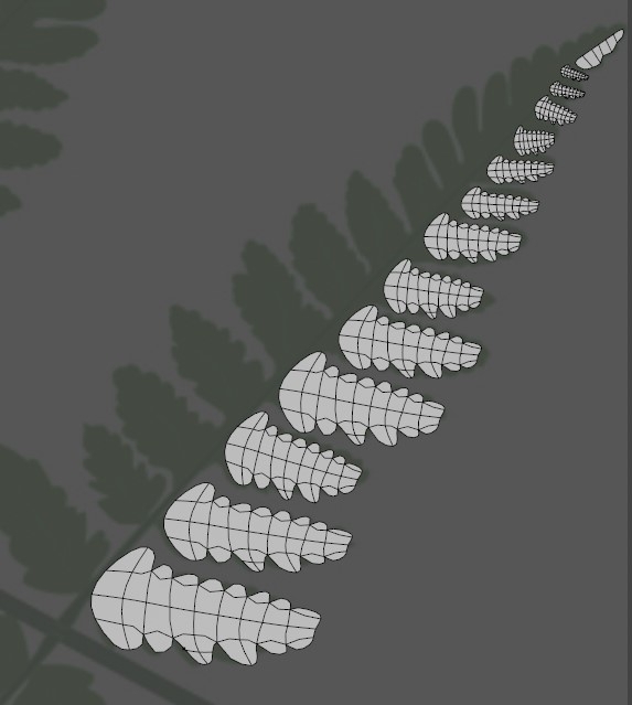
At this point I made an 'end section' as well, just out of simple polygons again and lined it up with my existing leaves.
6. Next step is collapse all those to a single model (select them all then Connect Objects & Delete), and mirror across to the other side. I used the Mirror Tool for this. Look that up on youtube as it's not so intuitive unless you know how). then I had a group I could offset and position to make the other side of the frond. At this point you may want to spend some time scaling and rotating individual poly islands within that mirrored side to get more variation, but I'm on a time one so I didn't here. If you do, just go into poly mode, and double click to select all the polys in one leaf.
At this point I selected all my polys and checked that my Normals were correct (they should all be orange facing up). If not use align / reverse Normals to fix.
Lastly for this bit I selected both models and CO&D'd them together into one.
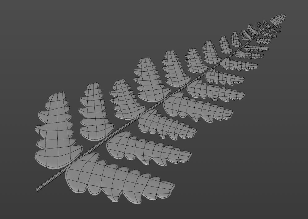
7. Now we just need to make the stem which I did with an 8 segment n-side profile and a simple path spline in a sweep, using sweep scaling to make it thinner at one end.. I also put my leaves mesh under a cloth SDS to add no subdivision but a tiny amount of thickness. With the cloth under regular SDS that looks like above...
Lastly we need some variation in all this - currently it has been easier to build everything flat, but now we need to curl stuff up a bit.
For this I got a displacer (deformer), which I made a child of the leaf. That got a (standard perlin) noise loaded into the shader / image field, and strength was set to very low so we got just gentle undulation. You may have to adjust the scale of the noise too, so experiment until you find the right settings. What we do need to make sure of is that the noise space is set to 'World' (noise settings). That way it will be different for every leaf later on in the model.
One problem you'll notice is that the displacement lifts the base of the leaves away from the stem. That is where you could add a box field into the falloff of the displacer to stop that happening.
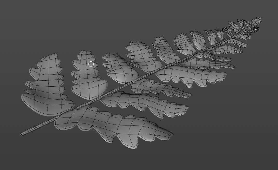
Finally (for this bit), you should have something that looks a bit like this, and we have our sub leaves ready to be cloned about into the bigger main leaf...
CBR
2 -
Yep I can show you how to model a fern. Give me half an hour, or so...
CBR
1 -
Here's a quick few stages on how to build a simple leaf...
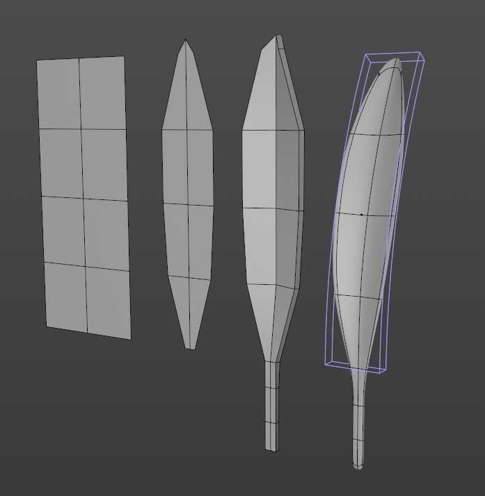
1. Start with plane, 4 x 2. Make editable, delete one half, place under symmetry.
2. Points mode, move points into general leaf shape.
3. Extrude (ctrl-drag) out the thin poly at the base a few times to make the stem. Pull border points of the leaf forward a little to get the center groove. Select all polys and add a little thickness with extrude (use caps). (We need thickness to make the leaf respond to light properly)
4. Pop the symmetry in a group null, then add a bend deformer to it as well, rotate until it is on the correct axis then use to bend the leaf something like shown. That group goes under L2 SDS to get the nice smooth result on the right there...
Next steps would be cloning a few of those into radial arrays and using random effectors on scale and rotation until we have a decent randomised complete plant that we can texture, and then collapse down into a single model when done...
CBR
1 -
This isn't too tricky if you break it down into small enough parts...
Start with the general scene composition, and make the base planes (ground / water) out of planes or Landscapes (with noise driven displacers).
Then work out what types of plants of you need, and make a list somewhere.You need 2 main types - the smaller, non-hero ones that you can clone everywhere and mush together into a general covering (possibly using hair), and then some hero plants that are dotted about or manually placed to get the effect you want. Either way, you can look around for free models on places turbosquid, etc or you can make your own, which is more effort obviously, but will give you more exactly what you want. Look at at LOADS of reference so you DO know what you want before you start

I like to start each plant model in a different file.
For each plant you need to work out what is the 'base unit' - ie for rushes it's a single leaf, whereas for ferns it's a complete fern frond containing many leaves etc.
And then you start to build those, very simply, out of polygons, using symmetry and bend deformers / cloning where you can, and group displacement in world mode, so that each leaf gets crumpled differently even if it's the same model..
When I have a section built I like to take a copy of that and combine it down to a single model that is easy to clone about in the main scene - that way your setup doesn't become a nightmare of multi-nested cloners !
So that's my general approach, but there are lots of ways to go about this.
Important not to forget the value of lighting in this sort of scene - I would be looking at some sort of volumetric god-rays type light to bump up the jungle feel. If you were feeling brave you could investigate caustics off the water surface !
If I get time later I will show you how to model a fern leaf OR you may find it quicker to just cut one out in photoshop and apply it to a (bend deformed plane), which is the cheat-y way to go if you haven't got the time or inclination to model these things properly... this is great for distant plants and in-game stuff, but doesn't stand up to close scrutiny or support cool effects like sub-surface scattering, which can add a lot to a scene...
CBR
0 -
I think you need to turn off background under Shading in the SnT master settings...
CBR
0 -
OK, now I look again I see the default cloner size changed as well, but none of these things should change its fundamental functionality...
CBR
0 -
It's R21. I think the size of the default sphere has changed - that is all.
CBR
0 -
That is correct - In R20 deleting points with polys is optional, so it is harder to create isolated vertices than it was in earlier versions (like where the tutorial was made). But you can still get them. Create a single polygon (primitives menu), make it editable, go to polys mode, select the poly and do shift+delete. In points mode you should see the points remain, and are now isolated. It was holding shift as you deleted the poly that left them there.
CBR
1 -
2 minutes ago, Igor said:
This is awesome, good job man... @Cerbera needs to look more closely into topology flow, but I think you will get Bad Ass Seal of Cerbera approval!

Lols. No, if it's KC I don't even have to look - I just know it will be excellent topo everywhere... his stuff sort of comes 'pre-wrapped' with my approval, not that he needs it !
CBR
0 -
Please update your profile to the correct version.
Thank you, yes that is a known / reported bug in R21.
CBR
1 -
8 hours ago, FrankDeFrank said:
The geometry is a bit messy.
How can I fix it?
Wow. Fixing that is most likely to require starting that section again IMO, or at least some form of complete retopology. Can't remember a time I saw a more appalling mesh !
CBR
0 -
You have to remember that not every system within Cinema works with every other system, and it looks like hair and spline-wrap are 2 such systems. If you think about this logically it is easy to see why this cannot work. The dynamics are telling the geo to do one thing, and the spline wrap is telling it to do something else. You need to find another way to animate the base object to which the hair is attached that doesn't actively prevent the hair dynamics working.
CBR
0


Randomly effect clones
in Animation - Do Not Post Here
Posted
Please update your profile to the version you are using....
Yep, the answer to most problems of this type in R20+ is fields
But the cafe has you covered - head to our own youtube channel and find the whole playlist about them.
CBR