

Cerbera
-
Posts
17,815 -
Joined
-
Days Won
698
Content Type
Profiles
Blogs
Forums
Gallery
Pipeline Tools
3D Wiki
Plugin List
Store
Downloads
Videos
Posts posted by Cerbera
-
-
Pls update your profile to the correct version.
No that's correct. The rest of them are greyscale only parameters. See manual.
CBR
0 -
Which problem - not clear on which object you are talking about !!
 Some pics would be good...
But I'll guess you mean the main screen for now, which I'd UV map with simple frontal projection like this...
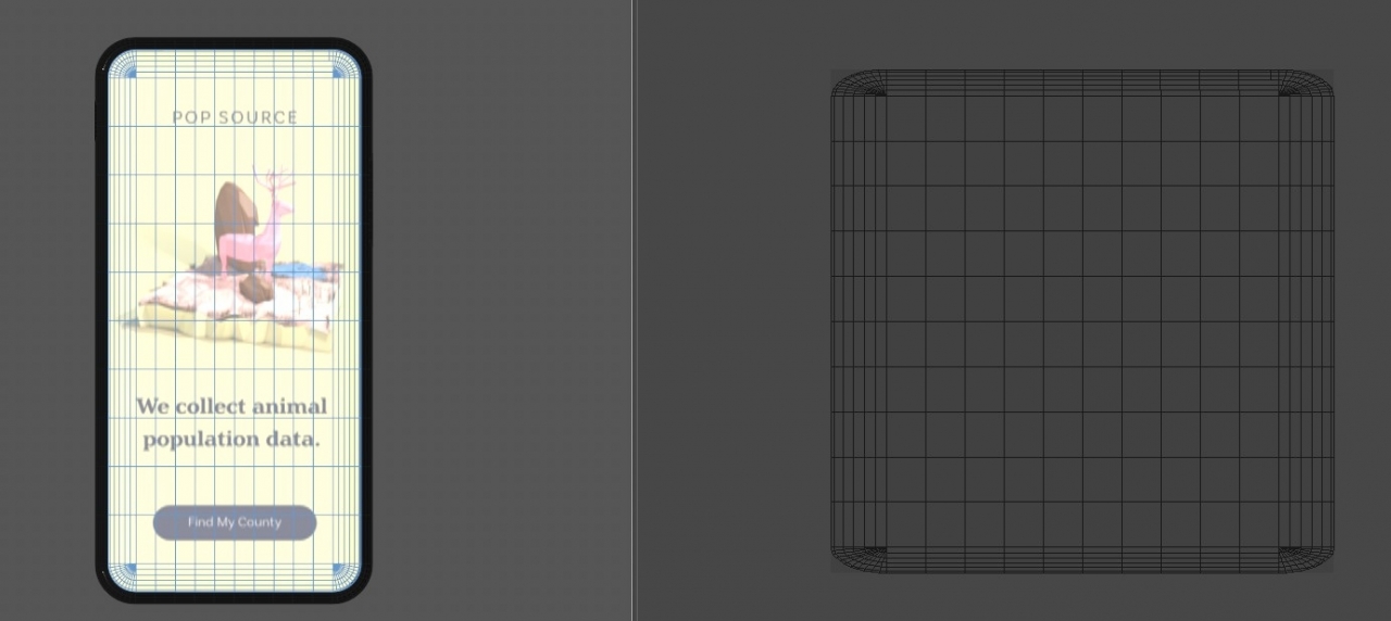
If that's the object you mean, then it's as simple as going to BP UV edit layout, selecting the object, its UV map, and all the polys, going to front view and hitting Frontal in the Projection types. Lastly I just did Fit UV to Canvas, and it's all good...
Also I should check you know about that ngon / non-terminated loop up there on the top right...
CBR
1 -
No, I don't think it is possible in the way you describe. Whether splines have their own IDs or not, that wouldn't make a difference to a sweep made out of them, which is just a generated new polygon object with its own texturing and UV coordinates. However, you can use a Correction Deformer and Transferred Polygon Selection tags to apply multiple materials to one sweep, so for practical purposes, the answer to your question is actually yes.
To do this make the Correction Deformer a sibling of the sweep within a group null, and use it to access the Poly mode, and double click each cable (or select one poly and do U,V), which should select all connected polys - ie all the polys of one part. Make a selection tag of that on the DEFORMER, then move that tag to the live sweep where you can use it to limit materials to that section.
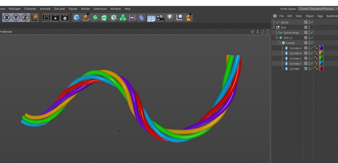
But I'd venture that a slightly quicker / simpler way to go here is to make cylinders / sweeps per 'cable', texture them independently, then arrange and group them as you need (I used a radial cloner for this) and spline wrap the whole lot into your final cable shape along the path spline you were originally using for your sweep. This sort of thing...
CBR
0 -
Have you tried caching the hair dynamics ?
CBR
0 -
I do have some ideas how we could possibly do this (or something broadly similar) in C4D without any plugins. For example, a blank hair object is a beautiful thing, into which you can just paint guides. So if you are using hair instancing you should be able to paint instanced plants in where you want them and then use hair's rather excellent randomisation / variation parameters to add as much of that as you need. Then you could switch to a different hair object, with different instances, and go about painting that over the top (both would be visible in the VP), repeating as needed. I appreciate this doesn't give you maps at the end of the day, but it is a practical way to paint in vegetation.
CBR
1 -
Cool cool. Yep. Align does need to be on for that...
CBR
0 -
In the Transform tab of the cloner, what happens if you just alter Z position ?
CBR
0 -
51 minutes ago, bezo said:
Maybe nobody in alfa/beta program use lower resolution monitor than 4k
I don't have a 4K monitor, but didn't notice any problem with it I could really criticize that wasn't just personal opinion - looks mostly great to me... sort of like a darker, nicer version of Modo, but I do also agree with comments I've seen noting that meshes are sometimes harder to see now...
And it is doing my head in a bit that everything's in different places
And shortcuts keep changing, so iI keep having to put them back...
CBR
0 -
5 hours ago, C4DS said:
golden snitch ... until profile picture gets changed

Yes, but now it's the dot from a laser pointer which the little cats love just as much
CBR
0 -
Oh OK I get ya...
What about cloning tiny luminant spheres directly onto every point in the cloud (using object/vertex mode) ? I've never tried that myself, but I reckon it might work...
CBR
0 -
Have you seen all this info here in the manual, which tells you how to generate a mesh from your point cloud ?
CBR
1 -
I think this has happened as Admins go through Cafe 2.0, revising and optimising stuff. It's nothing to worry about I'm told - you can just dismiss it...
CBR
1 -
18 hours ago, AlexisB said:
is the attached below called "Low Poly Modeling"?
No.
The term 'low-poly' is used to describe a few different things / different types of model in common 3D parlance...
1. Meshes designed for a game engine where low polygon count is crucial to performance. These meshes are usually 100% triangles and no subdivision, though that tends to be the case more historically, as game engines and hardware now don't impose quite the same limitations they used to, as technology improves.
2. Meshes involved in a sculpt or other retopology process that also have a high poly variant, where the term is used simply to distinguish between the 2 model versions.
3. Models in scenes that that are artistically or stylistically designed to use not enough polygons to describe the forms, and there are (usually) no phong tags (which reveals the faceting, and contributes to a 'low-poly' look)
So, if that is the case none of the pics above would be called 'low-poly' because they don't match any of the above criteria. These models are all silky smooth and non-faceted, so the term doesn't really apply here. As others have mentioned, I too would describe these as being 'primitive / deformer-based modelling', ie mostly very simplistic / easy to make, but don't use any special techniques other than a bit of basic poly (or SDS) modelling and what can be achieved with deformers etc...
CBR
1 -
4 minutes ago, Langley said:
Should it work with all kinds of selections i.e polys, edges and points?
Yes, contrary to what the manual says, that does work with all 3, even in R19.
CBR
0 -
8 minutes ago, Langley said:
When you say restriction tag, is that something you can in R20 and above? In R19 I dont see the option to save a selection tag for that deformer.
No, that's in all versions back to at least R10....
Create your selection tag on the OBJECT, then right click FFD, open Cinema 4D Tags, and Restriction is in there. Then drag your selection tag into the first of the fields in the restriction tag.
CBR
1 -
You're welcome. If you want to curve that front inset bit, FFD with restriction tag works a treat for that sort of thing...
CBR
1 -
I can open your file, and Ben was right - you have tons of intersecting clones at the start of the animation. But even if you solve that problem, a lot of the 2nd set of clones are also intersecting with Plane 2, which is also a dynamic collider, so has the same effect, stuff explodes upwards. Might be time to rethink the entire setup...
Hard to advise how you should do that - even though I have seen the scene file I still have no real idea what are you are trying to make or what the final effect should be !
CBR
1 -
0
-
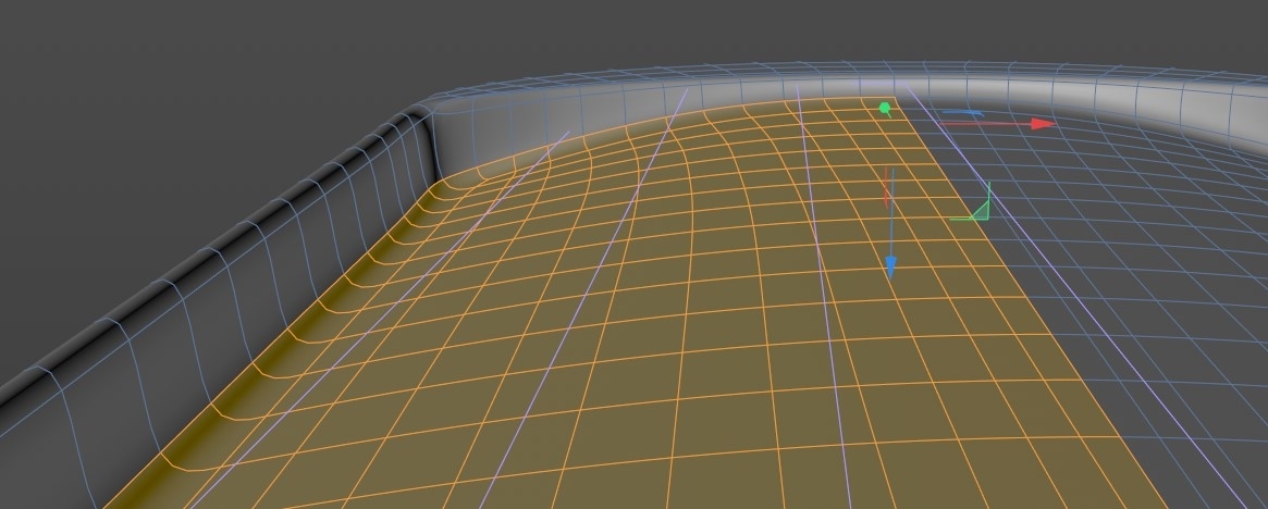
Yeah, I think it's something more like this...
I think at this sort of poly density we'd be needing an FFD to shape it now...
CBR
0 -
2 minutes ago, Langley said:
What do you reckon to this?
Well it's lovely and even and all that, but it's not useful topology for making that center divot
Hang on, I am still thinking about what is the ideal edge flow here...
CBR
1 -
Displacement is certainly an option, but I rather like the challenge of modelling it, so I'll tell you how to do that
You could use the steps I am going to describe either as the basis for your actual model, or just to give you the conforming ridges to treat separately...
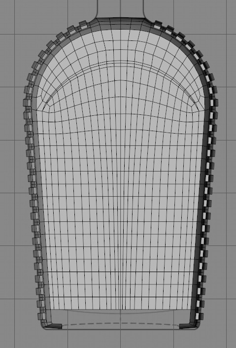
So I started with this, which I made from a plane and a bend deformer...

That got symmetried, cloned straight up, and placed inside a Connect, which I rotated to match the curvature of the bottle...
Then that went in a group null, and a further bend was applied to get the curve at the top, like so...
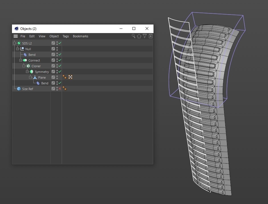
This exactly matches the reference, so is a good starting point for either approach I'd say.
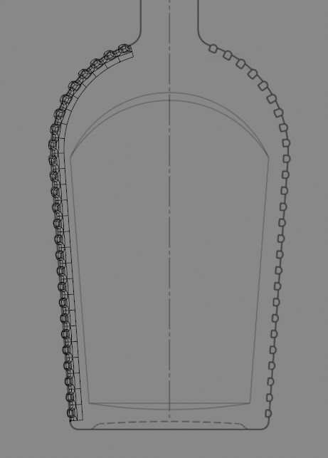
If you're doing it as separates, you don't need the outer rim, just the 'bump', whereas if basing your whole model on this you would use it as is with the surrounding wall intact. Next step would be taking an editable copy of this, symmetrying it across to the other side before bridging polys to the center line, giving you mesh you can continue to model into the final form, which shouldn't be too tricky, though would require some careful loop planning in the Y direction...
Does that makes sense ?
CBR
0 -
Welcome to the cafe
19 hours ago, Squibn said:Hope I've asked in the correct forum (First post!)
No, this question relates to DYNAMICS principally, so goes in....Dynamics ! - I've moved it for you.
However I am confused by your profile information. You say you are using C4D Lite, which doesn't have either Motext OR Dynamics, so that can't be right. Please update that to the correct version, which we need to know because often answers depend on that information. Perhaps have a read of the 'How to Post' thread...
CBR
0 -
Excellent - now I can see what we're trying to do
This is a glass bottle right ? If so, my first question would be 'why aren't we modelling the ridges directly into the main mesh ?', which is is the only solution that will look right in the render if this is made of glass. You can't use a boole AND subdivision so couldn't do it that way, so without modelling, curious to know how you were planning to combine your clones with the main mesh without that looking 'plonked on' in the render ? The only other way I can think of would involve the Volume builder, which you don't have if your profile info is correct...CBR
0 -
Oh OK, I sort of get your thinking
Have you got a photo or any other reference of the thing you're trying to make at all ?
CBR
0


C4DCafe Inbox Error?
in Miscellaneous - Do Not Post Here
Posted
It's OK, Admin knows He's working on that....
CBR