

Cerbera
-
Posts
17,814 -
Joined
-
Days Won
698
Content Type
Profiles
Blogs
Forums
Gallery
Pipeline Tools
3D Wiki
Plugin List
Store
Downloads
Videos
Posts posted by Cerbera
-
-
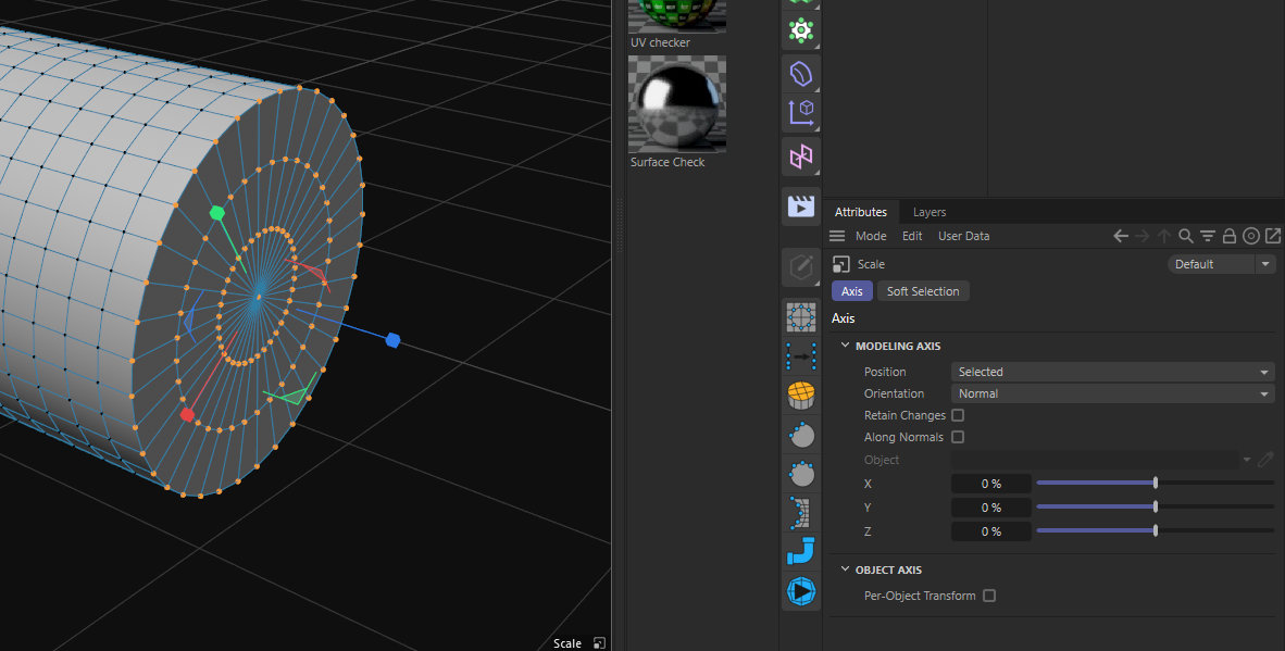
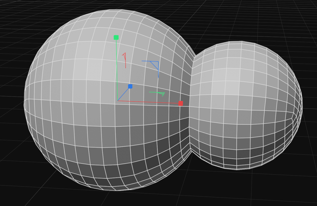
10 hours ago, Keith Vick said:
I'm trying to get these points back into a same position on the x so the end of my model is straight.
Click on the scale tool, and look in the attributes manager under the Axis tab. Orientation there is probably set to Axis, matching the overall model axis, which is probably wrong. So, easiest thing to do is change that setting to Normal, which should give you a gizmo with Z pointing straight out.
CBR
0 -
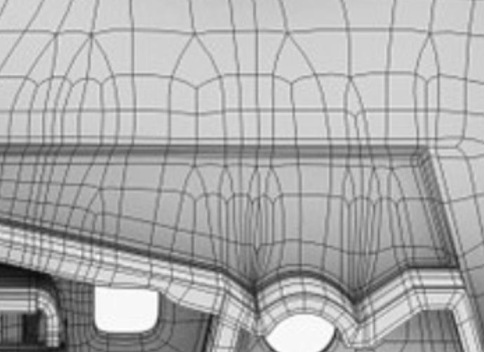
What you are seeing here is SDS-based tension Distortion, not UV distortion.
It is caused by the inconsistent polygon density, changing edge loop directions, and only half the control edges in place.
Therefore we need to change the underlying topology so the SDS distortion is much more confined in where it can run to. This we can achieve by doing 2 things:
1. Add another edge loop on the other side of the jutting out edge sections, and run this and its equivalent the other side up to the top where you can solve them back down again on a flat section away from borders where it doesn't matter. Like this...
2. Apply 1 level of subdivision to the mesh before you UV map it, which will increase resolution, which will restrict SDS distortion by half. Like this...
...which, when we UV that, and put it in a new SDS (max L2), then we find our SDS distortion has all but disappeared...
CBR
0 -
4 hours ago, prowl said:
Anyone else with a space mouse on a Mac? Not working on 2024... despite the recent new Maxon/3d Connexion driver,
Unfortunately, 3DConnexion's request to Maxon to remove their (Maxon's) previously perfectly functioning space mouse driver (version 2023.2.0) so that they can replace it with their own independently running one has been an absolute disaster as far as I can see, and the new driver they provide not only has terrible installation problems, but also has serious problems and negative effects on Cinema's stability for everyone I know that uses one including myself. I have never seen such a terrible case of self-sabotage from a company, and now I simply can't use my space mouse because it affects Cinema so negatively. I suggest you write to 3DConexxion like I did and complain vociferously, not that they appear to be listening. They seem to have a mistaken case of 'our driver is fine' syndrome, which it definitely isn't ! I am furious that I can't use my new Space Explorer in any version past 2023.1.2, and that they needlessly deprecated my previous model, which was still 100% perfectly functioning, and replaced it with a version that is deeply unreliable and unstable. Appalling behaviour.
CBR
1 -
41 minutes ago, jbatista said:
the option is active in one menu but in the viewport menu doesnt show as active
Thanks, you and HP - reported.
CBR
1 -
6 minutes ago, HappyPolygon said:
Where ? Didn't see that in the listed features ? Is this a capsule thing in the Asset Manager ?
Well yes, but it should be in the primitives menu !
 6 minutes ago, HappyPolygon said:
How could this benefit VB ? You mean melting two textured meshes together and transferring their textures to the VB ?
It means you can UV map a remeshed, easy-to-deal-with low res proxy of your several million poly VB creation, and then transfer the UVs to the high res original..
CBR
1 -
34 minutes ago, jbatista said:
Its a minor bug. But each time i activate the point vertex in the viewport the icon doesnt change its state to on. So it looks like its always off.
Sorry dude - not quite understanding what you mean there - could you elaborate ?
If I drag Point indexes to VP, then it does change colour for me to show it is on...

here moving from white (off) to purple (on)
CBR
0 -
Very glad to be able to talk about new things here at last. It's a VERY good release in my book...
Modelling department
- Subdivision Surface - now with linear pre-subdivision
- Normal Editing and proper control over normals (at last)
- Square weighted Phong shading / rendering
- Speed improvements are fairly huge for modelling too - deformers etc are no longer single thread.
- Pattern Select gives us very helpful new selection mode
- VAMP transfer of normals and UVs (for VB meshes)
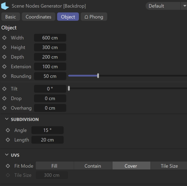
- New Backdrop Primitive
- Brush tool improvements / New Modes (surface smear / preserve boundaries)
and that's just in the modelling department. This release makes me very happy there.
And of course in the simulation department things got pretty good too, with Rigid Bodies joining the fully unified simulation system.
CBR
3 -
I think it's because when the computer sees it has more to do in one go it tries a bit harder. Sorry - couldn't resist.
CBR
1 -
33 minutes ago, Mash said:
you may have accidentally activated c4d's second axis lock tool.
Good spot there Mash - indeed 1 axis of his screenshot is white, which is what happens if the mystery lock is in place...
CBR
1 -
Welcome to the Core !
2 hours ago, Oliv formotion said:As in my screenshot : I'm in scale tool, no XYZ axis lock, in Model mode (not Object mode), and I can't find a way to have a uniform scale, even with CTRL or SHIFT, it only scales on 1 or 2 axis...
Make sure there are no axis locks in place, and then just get the scale tool, and click & drag anywhere in the viewport EXCEPT the gizmo, to scale uniformly on all axes !
Additionally you can enter size or scale values directly in the Coordinates manager (lower right hot-corner).
CBR
1 -
At the moment we only have a select few producing dedicated scene nodes tutorials, but I think we can expect more and more of those as the feature set becomes more refined and 'complete' (such as these things are ever complete!). I think they are wise to work more in the background producing a solid base for the future than they are publicising / training for it too widely while it is still a work-in-progress. I look forward to the future wonders of scene nodes but I think their real time to shine hasn't quite arrived yet...
CBR
2 -
Turn banking off in the sweep ?
Scene scale of 1 cm should be OK, but I concur it is very jittery and unstable.
I can lessen that by increasing substeps and damping in the sim scene globals, but I agree dynamics isn't playing nicely here...
I think I turned on sim before generators as well, which might have helped !
CBR
1 -
1 hour ago, HappyPolygon said:
For me the simplest/fastest way is this.
Pffft - yep, the cloner way is a far better and simpler plan than faffing about with XP / constraints, and I am quite cross it didn't occur to me !
 Nice one HP.
CBR
1 -
You could try a Constraint tag (clamp, surface mode), but I have always found those to be a bit sketchy and I struggle to get the calculation priority right. What about using Xpresso and a point node ?
CBR
1 -
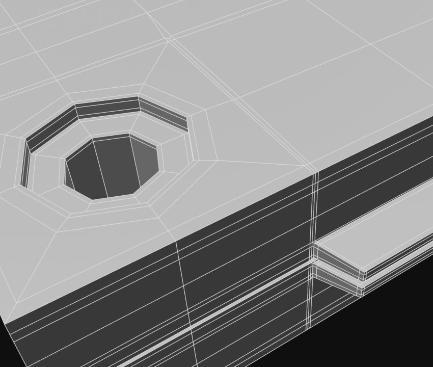
First of all - are you modelling the outside only or doing the inside as well ? If it's the latter then you should start with the inside, which better governs the polys you actually need.
What you have done here is fine but probably way too high poly - for example that hole on the corner should be able to be described with an 8 or 12 sided disc.
By starting so high poly you condemn yourself to wrangling that increased amount of them all the way across the model, rather than only having poly density you require.
CBR
0 -
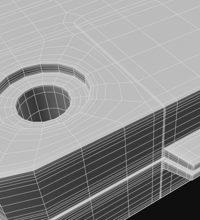
If we're going to do it nicely / properly, a cassette tape is actually quite hard to model in any software, but none of it is unsurmountable if you have good reference and plan your parts, corner types (box vs inset type) and topology carefully.
If you can get away with not modelling the inside (ie your cassette isn't clear material) then the outside is a lot easier than the inside, as your second reference shows...
You would begin this model by outlining the holes and tape guide section, and connecting those meshes together across what is (helpfully) a mostly flat surface, which means you can do any loop expansion / collapsing on flat bits, without worrying about SDS lumpiness on curvature. In that respect it is not strictly necessary to exclude tris or ngons in these areas, but in practicality it makes little sense, and saves little time to do so.
The front half of the case is notably simpler than the rear half, which contains all the extruded parts. It's not as much work as you'd think though, because we can deploy X-symmetry throughout, and all the parts that are chiral are best achieved with separate meshes...
But really your first reference photo is showing you all the prime topology points you have to hit to make that inside, which mainly consists of ensuring you have enough topology to describe the hard edged inner details at the bottom, which then collapses down to less dense poly flow as they get further up where detail is less. Hence the liberal use of kite quads for loop concatenation as we see particularly in the section below...
Note the box cornering that goes on everywhere there is a hard defined corner, which is required to stop this collapsing under SDS.
Of course there are a number of lazier, cheat-ier ways to make the modelling easier (booles, volume builder, non SDS etc) but none of those will give you quite as nice results as if you model it poly by poly, SDS, where you have infinite resolution suitable for extreme close-ups. But if this cassette is just lying on a table somewhere at the back of a scene, then a full SDS model is probably overkill.
CBR
0 -
At the risk of sounding like a broken record, it would be helpful to have the scene file here...
But it looks like your character has unsuitable topology to deform properly when rigged, especially around the groin area.
In any case we need to see what your weighting is doing before we can properly advise...
CBR
1 -
I'd go Boole then ReMesher - perfect job, lovely topo. And then you could put that under Thicken or Cloth Surface then SDS, and you're done...
CBR
2 -
14 minutes ago, smoore said:
Is there not a way to stop deformers calculating on objects that aren't visible in the viewport?
As Mash said, only by turning them off.
I suppose another option is the mesh deformer ? Deform your lower poly model instead, and use it as proxy for high res model...
CBR
0 -
Some questions:
What version of Cinema is this ?
How many polys are we talking about ?
Have you tried reducing the polycount via remeshing etc ?
CBR
1 -
I would suspect Normals too. If there is still a Normal tag on your object, remove it. Then select all polys to check all facing camera are orange (Normals correct) rather than blue (Normals reversed). Lastly, in the phong tag you could uncheck 'Use edge breaks' to eliminate the last of the possibilities that might cause this. If still problems, then might be worth running an optimize to check there aren't any disconnected polys...
CBR
0 -
-
Here is a comparison of 3 of the available mapping methods.
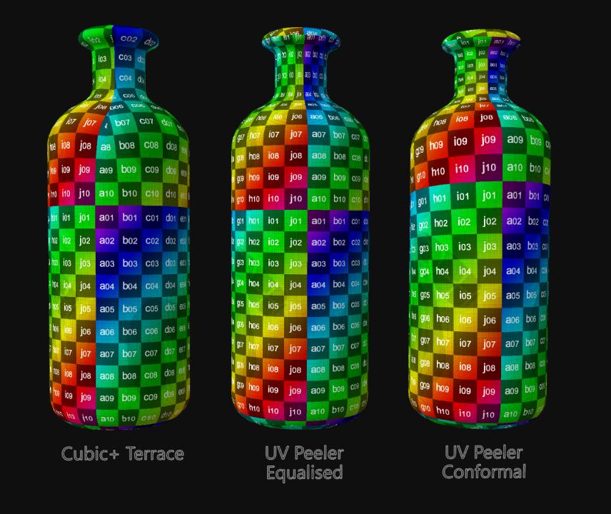
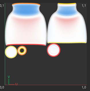
As we can see the cubic terraced islands approach produces by far the least distortion. The not inconsiderable distortion we inevitably get from any version of the UV peeler method is quite extreme if you do the outer and inner as just the single island, even in the conformal relaxed version (image C above) so by doing a cubic approach we spread that distortion out across the 4 areas we allow to remain separate, which lessens it accordingly. The price we pay for this is 4 partial seams per island*
* You may notice that in A, the Cubic version I added a lot more seams than that along the base end to achieve zero distortion in that area, knowing that we probably won't see any seam lines down there...
Note in the main top pic how the squares stay the same size at the bottom of the bottle all the way to the top, whereas the UV peeled ones can help but shrink those polys the higher up the bottle we go, which is why solution A is better, albeit non-intuitively so.
Make sense ?
CBR
0 -


Cinema 4D UV View Port Freeze Issue
in Cinema 4D
Posted
Most probably linked to graphics card driver. I have an identical hardware setup to you, and sometimes get that, though not in the UV view any more than any other I would say. At least we can save before we restart ! Maxon is aware, but it's a very difficult issue to diagnose as it doesn't generate error reports.
CBR