

Cerbera
-
Posts
17,814 -
Joined
-
Days Won
698
Content Type
Profiles
Blogs
Forums
Gallery
Pipeline Tools
3D Wiki
Plugin List
Store
Downloads
Videos
Everything posted by Cerbera
-

Cinema 4D Moving along axis not working
Cerbera replied to Marcos Devoto's topic in Miscellaneous - Do Not Post Here
Is your shift key stuck down ? CBR -
Cinema 4D Animated Textures not working ?
Cerbera replied to SophiaWang's topic in Modelling - Do Not Post Here
This has been marked solved. Pls post your solution ! CBR -
Cinema 4D How was this done?
Cerbera replied to Spencer Fanuka's topic in Animation - Do Not Post Here
Cubes cloned onto plane which is displaced by animated noise, then affected by random Effector doing Y position ? CBR -
Cinema 4D How to Stop Hair from Animating
Cerbera replied to AlexisB's topic in Animation - Do Not Post Here
1. Turn off hair dynamics. 2. That will look very unnatural if you do that. Much better to leave it on, and then use forces to direct the movement. CBR -
Which version of Cinema are you using ? CBR
-
Cinema 4D Baking the display tag keyframes
Cerbera replied to daddycoull's topic in Rigging - Do Not Post Here
Yeah I'm not surprised that doesn't work. Whilst FBX format does have visibility channels, we can't currently address them as far as I know, and certainly not in versions before R18... Nor can we use Object On / Off properties via the traffic lights, or 'enabled' keyframes... But I think we can use scale. So that's what I'd try next. At the start of the animation keyframe Object Scale to 0, copy that to the frame before you want it to switch 'on', then in the next frame scale it to 100% and key that. Then let us know if it works ! 🙂 CBR -
You can call them whatever you like as long we know which ones we're talking about :) To me they are Y-loops simply because they flow around the Y axis ( the axis that goes up and down) but if you visualize or describe them differently that's fine too - you would have an equally strong case to describe them as XZ loops... CBR
-
You can zip it, or upload to dropbox and link it here instead... CBR
-
Yes we will need the scene file pls... CBR
-
Look how much nicer your body section is now I've removed half the Y loops from it... But what we can't save is the holes - there is just not enough topology here to adequately describe them, so you get this horrendous SDS bulging around them. The solution is to use a lot more polygons in this area at the start. You need at least 16-24 radial segments to have enough topology there to support a hole of that size and sharpness, not the 6 you have now, which is below the minimum 8 that SDS needs to be able to produce a circular form. So for that reason you should model the torso without any holes until you have applied the SDS, and then you can get the result you are looking for without the horrible deformation. Here's one I did via that method.... note how perfectly smooth the overall form is whilst also having lovely straight edged non-bulgy cutouts... This is possible because I started my 'leg' with a cylinder with 16 sides (left) and enough height segments to give me perfect squares, then doubly established my curvature (by making the L2 SDS editable - middle) before I removed the holes. How did I know which polys to remove when they were that subdivided ? I simply selected them before I had applied the SDS, which preserves that selection even when the SDS has been made editable. Because my polys started out so even and regular, even if I was to put this mesh under a further SDS object now (right), it would still look great, and there would still be no unattractive pinching / deformation because at every stage I have given SDS exactly what it wants to work with. If you want your cutouts to have perfectly straight corners you can stop at stage 2 (middle), but I think we should add that final (just level 1) SDS (right) as it subtly rounds the corners in quite a pleasing way... Does that make sense ? CBR
-
Cinema 4D Signage Animation Suggestions Please
Cerbera replied to StageFive's topic in Rigging - Do Not Post Here
That's a reasonable way of doing that, and Mospline could do it for us here, but just as easy to get 2 bend deformers to do the same thing... 'Keep Y axis length' ticked to preserve the length.... CBR -
Cinema 4D Signage Animation Suggestions Please
Cerbera replied to StageFive's topic in Rigging - Do Not Post Here
Yes, this is exactly the sort of thing I had in mind with that category ! :) Not so much. MoGraph's primary use is in making lots of objects do broadly similar things in a largely procedural sort of way, so I'd say it doesn't have much application here, where you need 1 or 2 items doing very specific things at specific times. I would tackle both those ad-board animations in Cinema exactly as you have been doing in other programs, via simple keyframed PSR and deformer animation, which Cinema can also handle admirably... we just need to make sure your hierarchy in the Object Manager is set up in the most helpful way to achieving that animation... For me that involves animating mostly nulls, which then contain the actual objects I need to move and transform. That way, the client can have all their mad ideas and changes, and your animation never needs redoing because you animated the nulls and not the objects within them ! In the case of your bendy ad-boards you may not even have to resort to 'full' point level animation - there are numerous deformers (bend seeming to jump highest in this case) that can be keyframed as easily as PSR, or, for more difficult deformations there is the vastly powerful Pose-Morph which is a way of doing point level or pose-based animation via simple sliders, which can also be keyframed. CBR -
Workflow: find a halfway point/nattering
Cerbera replied to jericsynrgy's topic in Modelling - Do Not Post Here
No, that's just a disc primitive (under symmetry) in which I am playing with the slice end parameter. If we're just talking about a single edge we can just use Mid Point Snap to instantly find the middle of it, but with whole organic meshes it's a slightly more oblique process.. But let's think about this - the Coordinates Manager is very useful here in that it shows you scale dimensions based on the BOUNDING BOX around a mesh (you can even see those bounding boxes by setting display mode to Box), and the Object Axis of diligently created models should be exactly in the center of any object you create. And because you can also snap to the Axis, then that is often the fastest way of finding the middle of something - there is rarely a need to do it numerically. But if we do need to know exact figures, then the Scale properties of the Coordinates Manager will tell you, and the half way point along any particular axis will be half the value displayed there (provided the CM is in Object Mode). That works really well UNLESS the polys in the object have become rotated off-axis, in which case the CM cannot know this, and its reports remain based on what the Object Axis is doing, so you need to be aware of that before relying on that method. Lastly, have a look at the Measure and Construction Tool - this is not very intuitive, but once you've watched a Youtube video or 2 and understood the way it works it can be used (in conjunction with snapping) to accurately measure and set distances irrespective of poly or model rotation. However I would say in terms of practical day-to-day use you should almost never have to turn to this if your axes are just set correctly in your model ! CBR -
Sub-D modelling is an art form that takes many years to perfect. But general guidelines apply... whenever there is pinching or rippling in a Sub-D model it is because there is something wrong with the underlying topology. That can be either: Non-quad polys Complex Poles Polys with inferior flow or degenerated / manifold edges Non-regular polys Not enough polys to describe form Too many polys to describe form General sloppiness / uncareful modelling As has been mentioned, your mesh has loads of isolated vertices, and the odd n-gon which will risk causing some problems later (though I note it isn't yet !), but overall, other than being a little dense in one direction (Y) and a little sparse in another (Z), it is largely OK. But you do have SDS set to Level 4, which is way high for this sort of model - L3 should be the absolute maximum you need here, with L2 being preferable. This matters because SDS artifacts become more noticeable the higher the subdivision level. So whilst your mesh is pretty regular and mostly even (good things) because it is a little dense on Y as well, you are still having to wrangle many more points than you ideally could, and this can also result in SDS 'rippling' because it is hard to maintain flow and consistency across neighbouring edge loops when there are so many of them. That, combined with slightly too few polys along Z, is what are probably the main issues here... CBR
-
Workflow: find a halfway point/nattering
Cerbera replied to jericsynrgy's topic in Modelling - Do Not Post Here
You could use the HUD. If you have turned on selected points, edges and polys you could use path select to select the edges along one side of the form, noting the total. Then just ctrl marquee deselect what looks like half, and see if the HUD reports half the number you noted earlier. But faster to just start again with a new cylinder / disc, which will arrive perfectly aligned to world center and you can use the slice options within them to adjust the slicing numerically... Personally I'd get symmetry involved from the word go, but you can still use that in conjunction with slice to make sure you get a slice that happens evenly across an axis. CBR -
Cinema 4D Visibility hotkeys: suggestions
Cerbera replied to jericsynrgy's topic in Miscellaneous - Do Not Post Here
It is nice being able to customize your shortcuts. Personally I just have the icons for Hide Selected / Show All / Set Selection in my interface... CBR -
(R17) splitting polys at specific points
Cerbera replied to jericsynrgy's topic in Modelling - Do Not Post Here
It is a basic function of the knife tool (line mode, or Line Cut in R18+). OR you can select both points and hit M,M for Connect. Or use the Polygon Pen - that too can cut across a single poly. CBR -
Cinema 4D Shoulder and arm rig
Cerbera replied to ROMAN ZHAMALETDINOV's topic in Animation - Do Not Post Here
I would do this entirely with hierarchy myself, but that might be because I am far less expert with joints and IK than I am with nice simple rotations.... CBR -
Attach object to animated spline
Cerbera replied to TSdesign's topic in Modelling - Do Not Post Here
Yep, it's not quite as simple as Align to Spline... we need to get some Xpresso out of the box as well... https://youtu.be/hh8WzVI0qyU CBR -

From the album: Current Stuff
-

From the album: Current Stuff
-

From the album: Current Stuff
-

From the album: Current Stuff
-
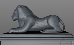
From the album: CBR Model Wires
-
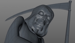
From the album: CBR Model Wires